48 Rockwell Automation Publication 5094-UM001C-EN-P - April 2019
Chapter 2 Common Digital I/O Module Features
Software Configurable
You use the Logix Designer application to configure the module, monitor system
operation, and troubleshoot issues. You can also use the Logix Designer
application to retrieve the following information from any module in the system:
• Serial number
• Firmware revision information
• Product code
•Vendor
• Error and fault information
• Diagnostic information
By minimizing the need for tasks, such as setting hardware switches and jumpers,
the software makes module configuration easier and more reliable.
Fault and Status Reporting
The FLEX 5000 digital I/O modules report fault and status data along with
point data. Fault and status data is reported in the following ways:
• Logix Designer application
•Module status indicators
For more information on fault reporting, see the individual module feature
chapters and Appendix A
, Troubleshoot Your Module on page 123.
Module Firmware
The FLEX 5000 digital I/O modules are manufactured with module firmware
installed. If updated module firmware revisions are available in the future, you
can update the firmware.
Updated firmware revisions are made available for various reasons, for example,
to correct an anomaly that existed in previous module firmware revisions.
Firmware information for I/O devices is available at the Rockwell Automation
Product Compatibility and Download Center (PCDC). The PCDC is available
at: https://compatibility.rockwellautomation.com/Pages/home.aspx
At the PCDC, you can use the module catalog number to check for firmware
updates. If the catalog number is not available, then no updates exist.
Verify that the firmware revision of the FLEX 5000 I/O modules that you use is
correct before commissioning the system.
STATUS
POWER
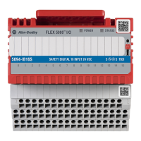
SAFETY DIGITAL 16 INPUT 24 VDC
5094-IB16S
5
5
TB3I
FLEX 5000
TM
I/O
0 1 2 3 4 5 6 7 8 9 10 11 12 13 14 15
STATUS
POWER
DIGITAL 16 INPUT 24 VDC
5094-IB16
1
1
TB3
FLEX 5000
TM
I/O
0 1 2 3 4 5 6 7 8 9 10 11 12 13 14 15
Safety Modules
Standard Modules
STATUS
POWER
SAFETY DIGITAL 16 INPUT 24 VDC
5094-IB16S
5
5
TB3I
FLEX 5000
TM
I/O
0 1 2 3 4 5 6 7 8 9 10 11 12 13 14 15
STATUS
POWER
DIGITAL 16 INPUT 24 VDC
5094-IB16
1
1
TB3
FLEX 5000
TM
I/O
0 1 2 3 4 5 6 7 8 9 10 11 12 13 14 15
Safety Modules
Standard Modules
IMPORTANT Do not use the module status indicators or I/O status indicators on
FLEX 5000 I/O safety modules for safety operations.
STATUS
POWER
SAFETY DIGITAL 16 INPUT 24 VDC
5094-IB16S
5
5
TB3I
FLEX 5000
TM
I/O
0 1 2 3 4 5 6 7 8 9 10 11 12 13 14 15
STATUS
POWER
DIGITAL 16 INPUT 24 VDC
5094-IB16
1
1
TB3
FLEX 5000
TM
I/O
0 1 2 3 4 5 6 7 8 9 10 11 12 13 14 15
Safety Modules
Standard Modules
IMPORTANT Only download firmware and access product release notes from the
Rockwell Automation PCDC.
Do not download firmware from non-Rockwell Automation sites.
 Loading...
