Rockwell Automation Publication 2071-UM001E-EN-P - November 2013 123
Interconnect Diagrams Appendix A
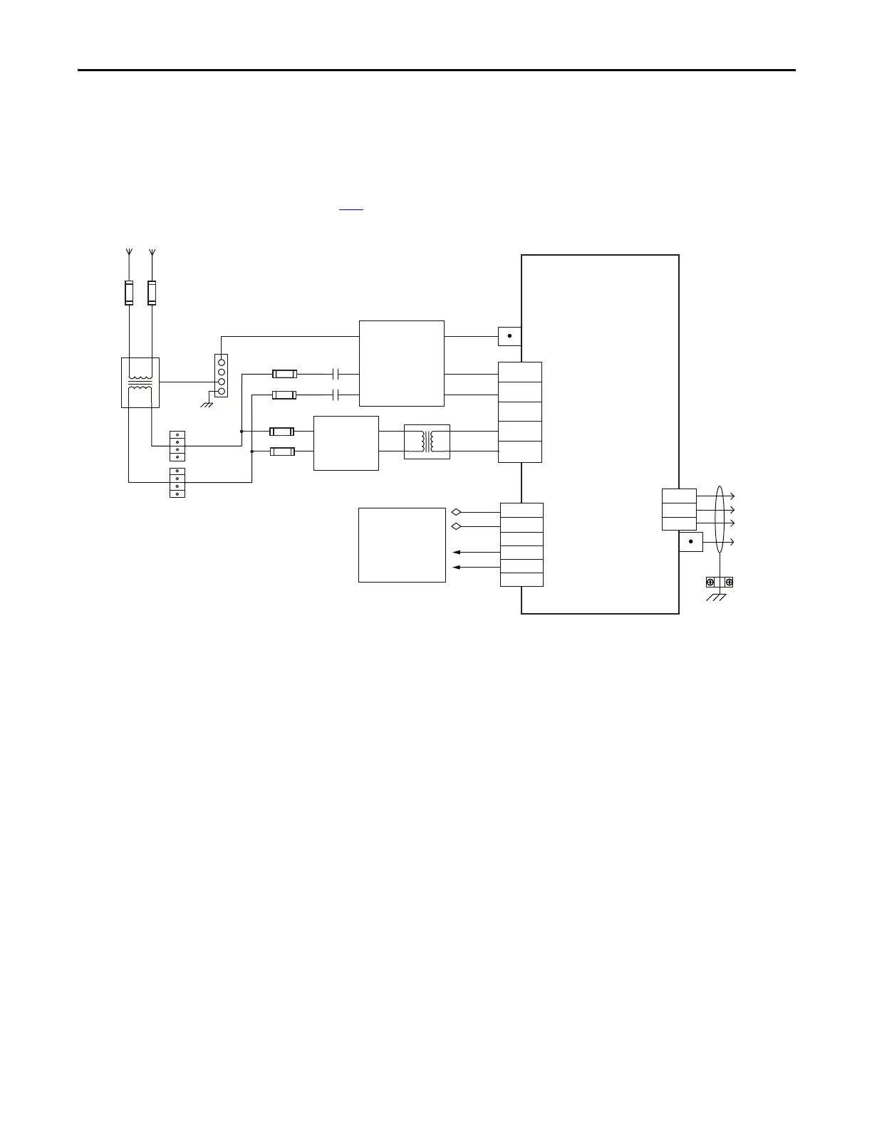
Power Wiring Examples
You must supply input power components. The single-phase and three-phase line
filters are wired downstream of fusing and the M1 contactor.
Figure 50 - Kinetix 3 Drive Wiring Example (230V single-phase input power)
24V IN
SV-ON
RDY +
RDY-
L1
L2
2
3
41
42
U
V
W
L1
L2
L3
L1C
L2C
Single-phase AC Input
230V AC RMS, 50/60 Hz
Notes 1
Isolation
Transformer *
Bonded Cabinet Ground Bus *
Ground
Screw
Input (IPD)
Connector
Fuse Disconnect
or Circuit Breakers
Input Fusing *
Note 2
M1 *
Notes 5, 6
Use discrete logic or
PLC to control SV-ON
(ENABLE) to drive and
monitor RDY signal
back from drive.
Refer to Attention statement (Note 8).
Three-phase
Motor Power
Connections
Note 9
Motor Power
(MP) Connector
Cable
Shield
Clamp
Note 7
I/O (IOD)
Connector
Note 11
To
Motor
2071-Axx
Kinetix 3 Drive
* Indicates User Supplied Component
Refer to table on page 122 for note information.
2090-XXLF-
TC116xx*
AC Line Filter
(optional)
Ground
Screw
AC Line Filter*
(optional)
Isolation
Transformer *
 Loading...


