Rockwell Automation Publication 2071-UM001E-EN-P - November 2013 27
Install the Kinetix 3 Drive System Chapter 2
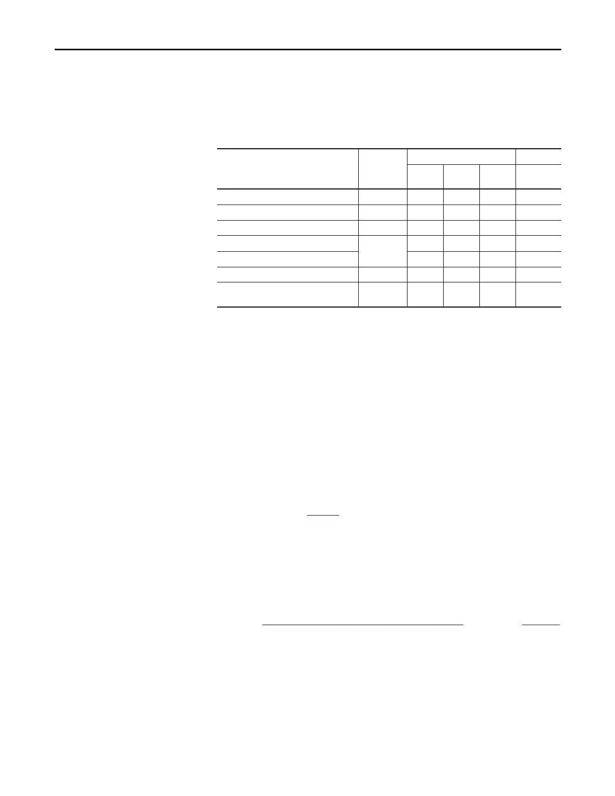
Cable Categories for Kinetix 3 Drive Components
This table shows the zoning requirements of cables connecting to the Kinetix 3
drive components.
Table 4 - Kinetix 3 Drive Components
Noise Reduction Guidelines for Drive Accessories
Refer to this section when mounting an AC line filter or shunt resistor module
for guidelines designed to reduce system failures caused by excessive electrical
noise.
AC Line Filters
Observe these guidelines when mounting your AC line filter:
• If you use Bulletin 2090 AC line filter, mount the filter on the same panel
as the Kinetix 3 drive and as close to drive as possible.
• Good HF bonding to the panel is critical. For painted panels, refer to the
examples on page 24
.
• Segregate input and output wiring as far as possible.
Motor Brake
The brake is mounted inside the motor. How you connect to the drive depends
on the motor series.
Refer to Kinetix 3 Drive/Rotary Motor Wiring Examples
beginning on page 124
for the interconnect diagram of your drive/motor combination.
Wire/Cable Connector
Zone Method
Very
Dirty
Dirty Clean
Shielded
Cable
L1, L2, L3, L1C, L2C (unshielded cable) IPD X
U, V, W (motor power) MP X X
Motor feedback MF X X
Analog outputs
IOD
XX
Others X
Analog output A.out X
Serial Communication
Comm0A
Comm0B
XX
 Loading...


