22 Rockwell Automation Publication 2071-UM001E-EN-P - November 2013
Chapter 2 Install the Kinetix 3 Drive System
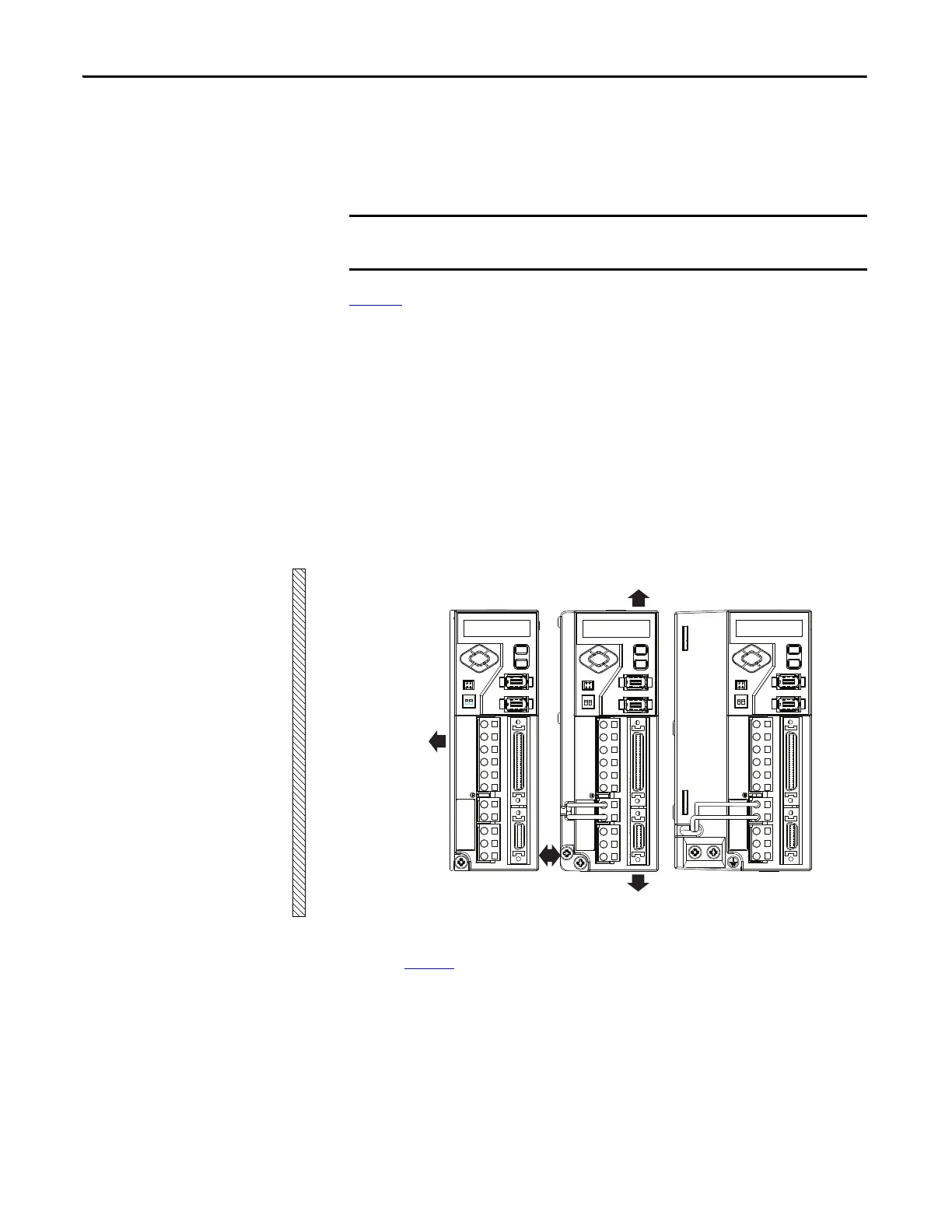
Minimum Clearance Requirements
This section provides information to assist you in sizing your cabinet and
positioning your Kinetix 3 drive system components.
Figure 4
illustrates minimum clearance requirements for proper airflow and
installation:
• Additional clearance is required depending on the accessory items
installed.
• Additional clearance is required for the cables and wires connected to the
front of the drive.
• An additional 150 mm (6.0 in.) is required when the drive is mounted
adjacent to noise sensitive equipment or clean wireways.
See Kinetix Servo Drives Specifications Technical Data, publication
GMC-TD003 for Kinetix 3 drive dimensions.
Figure 4 - Minimum Clearance Requirements
Refer to page 21 for power dissipation specifications.
Mount the module in an upright position as shown. Do not mount the module
on its side.
50.0 mm (2.0 in.) clearance
for airflow and Installation.
10 mm (0.39 in.)
clearance between drives.
30 mm (1.18 in.) clearance to
side wall of enclosure.
50.0 mm (2.0 in.) clearance
for airflow and Installation.
 Loading...


