124 Rockwell Automation Publication 2071-UM001E-EN-P - November 2013
Appendix A Interconnect Diagrams
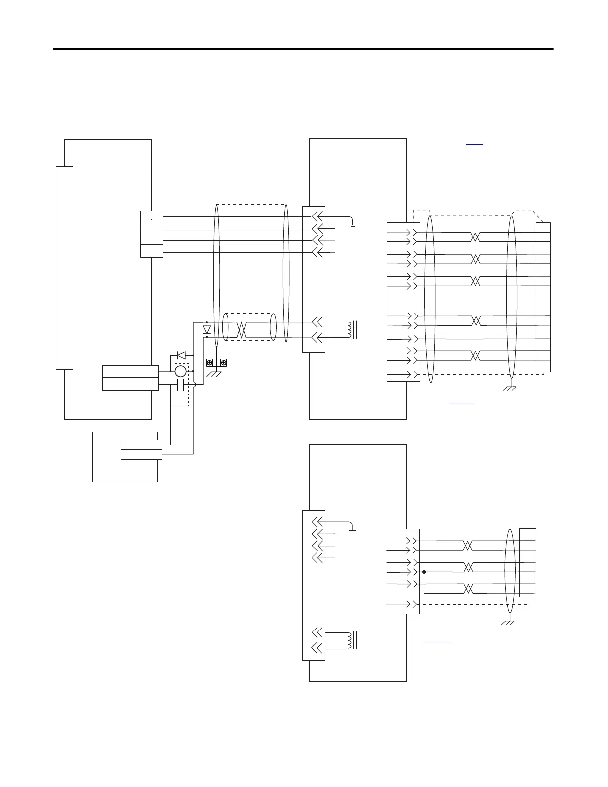
Kinetix 3 Drive/Rotary Motor Wiring Examples
These wiring diagrams apply to Kinetix 3 drives with compatible rotary motors.
Figure 51 - Kinetix 3 Drive (230V) Wiring Example with TL-Series (TLY-A) Motors
5
3
2
1
MBRK+
MBRK-
7
9
W
V
U
GND
GREEN/YELLOW
BLUE
BLACK
BROWN
BLACK
WHITE
W
V
U
AM+
AM-
BM+
BM-
IM+
IM-
+5VDC
ECOM
WHT/BLUE
GREEN
WHT/GREEN
GRAY
WHT/GRAY
BLACK
WHT/BLACK
RED
WHT/RED
3
4
5
6
7
8
20
1
10
S1
S2
S3
YELLOW
WHT/YELLOW
14
16
SHIELD
22
23
15
24
17
19
9
10
11
12
13
14
0
1
2
3
4
5
6
7
8
9
10
11
12
13
14
15
16
17
18
19
20
MBRK-
MBRK+
5
3
2
1
7
9
W
V
U
+5VDC
ECOM
GRAY
WHT/GRAY
22
23
20
1
24
GND
SHIELD
BAT+
BAT-
ORANGE
WHT/ORANGE
6
BAT+
BAT-
DATA+
DATA-
GREEN
WHT/GREEN
13
14
10
13
CR1
OUTPUT3- (BK-)
OUTPUT3+ (BK+)
24V DC
24V DC COM
48
47
Motor Brake
Three-phase
Motor Power
Motor
Feedback
TLY-Axxxx-H (230V)
Servo Motors with
Incremental Feedback
2090-CFBM6DF-CBAAxx (flying-lead)
Feedback Cable
Note 9
I/O (IOD)
Connector
Note 4
Motor Power
(MP) Connector
2071-Axx
Kinetix 3 Drive
Motor Feedback
(MF) Connector
2090-CPBM6DF-16AAxx
Motor Power and Brake Cable
Note 9, 10
Use 2090-CPWM6DF-16AAxx
cable for non-brake applications.
User Supplied
24V DC
Refer to table on page 122 for note information.
TLY-Axxxx-B (230V)
Servo Motors with
High-Resolution Feedback
Cable
Shield
Clamp
Note 7
2090-CFBM6DF-CBAAxx (flying-lead)
Feedback Cable
Note 9
2071-TBMF
Motor Feedback
Breakout Board
Refer to Motor Feedback Breakout
Board Installation Instruction
Publication 2071-IN003
for proper
grounding technique.
Refer to Motor Feedback Breakout
Board Installation Instruction
Publication
2071-IN003
for proper grounding
2071-TBMF
Motor Feedback
Breakout Board
with battery installed
 Loading...


