Rockwell Automation Publication 2071-UM001E-EN-P - November 2013 79
Chapter 5
Using the Keypad Interface
Keypad Input
The operator interface provides immediate access to the Kinetix 3 drive status
displays and monitoring, parameter settings, and functional commands. The
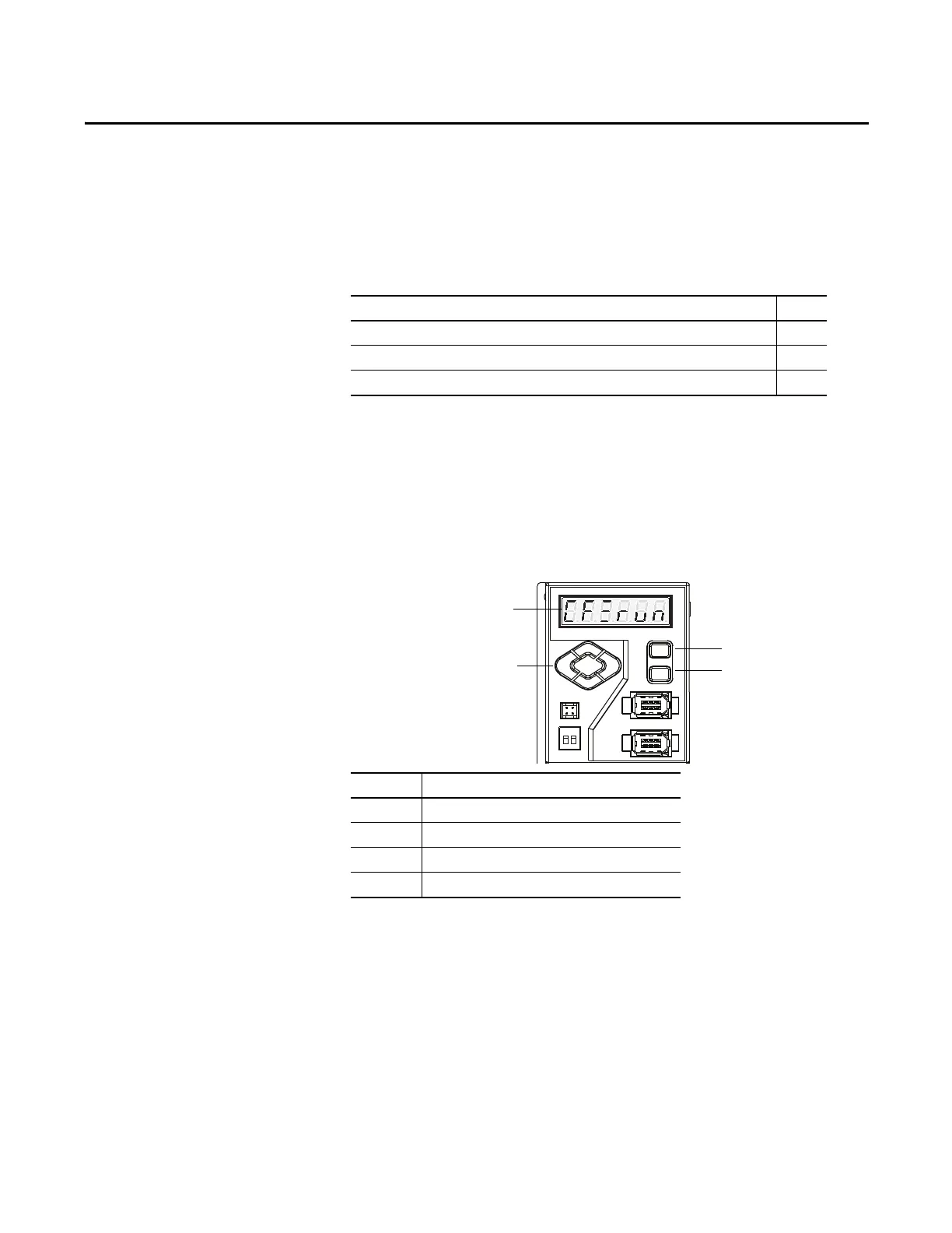
features of the Kinetix 3 drive operator interface are identified in Figure 44 and
described below.
Figure 44 - Kinetix 3 Operator Interface
• The 7-segment status indicator displays status, parameters, function
commands, and provides drive monitoring.
• The Control Power illuminates when the drive's control electronics are
powered by application of 200…230V power to the L1C, and L2C
Control Power pins.
• The Mode/Set, and Enter keys provide the operator with access to drive
functions. The directional keys (Up, Down, Left, and Right) edit drive
function settings. These keys let the operator monitor and change the
drive’s program.
Topic Page
Keypad Input 79
Status Display/Operation Mode 81
Reset Drive to Default Value 83
Item Description
1 7-segment status indicator
2 Up, down, left, and right directional keys
3Mode/Set key
4Enter key
 Loading...


