34 Rockwell Automation Publication 2071-UM001E-EN-P - November 2013
Chapter 3 Kinetix 3 Drive Connector Data
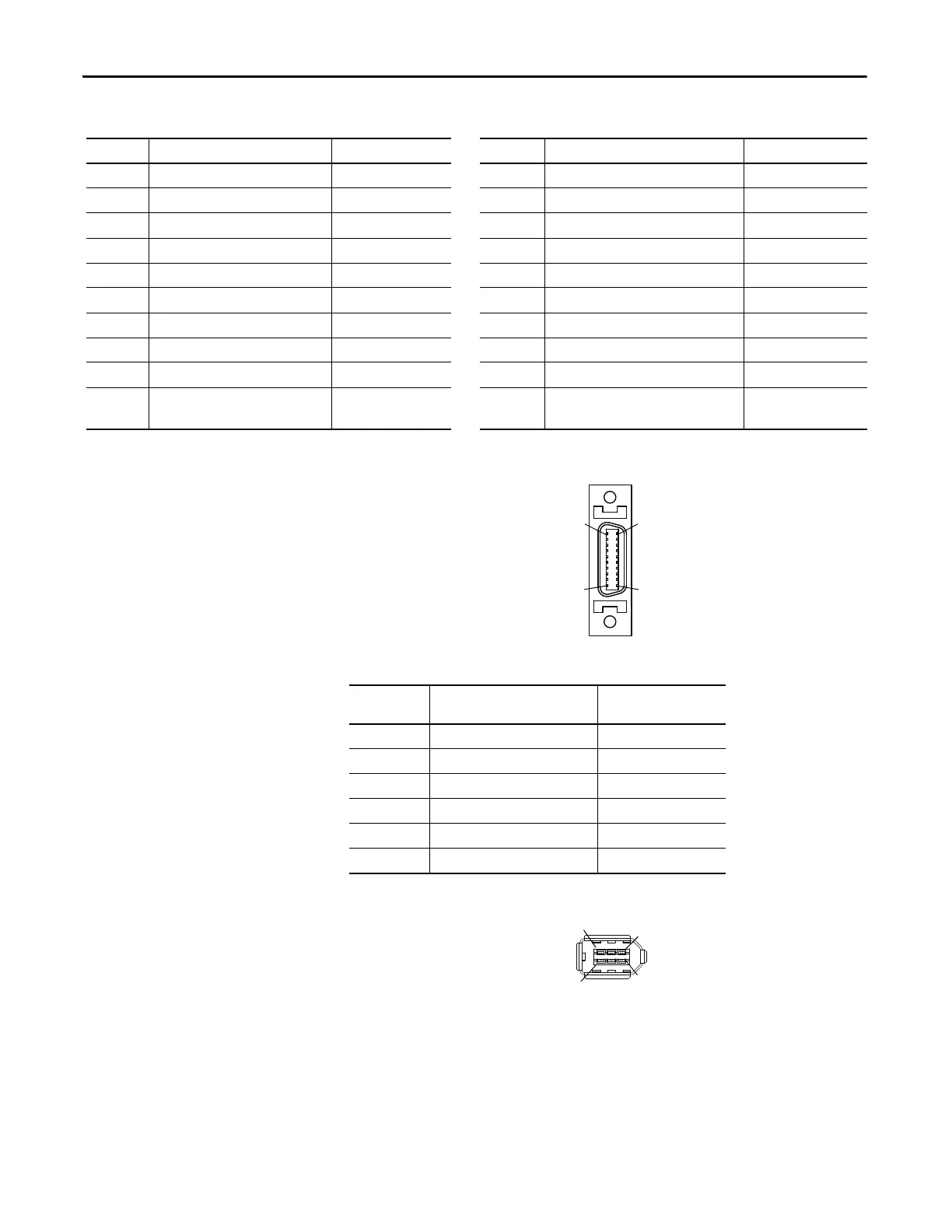
Motor Feedback (MF) Connector Pinout
Figure 11 - Pin Orientation for 20-pin Motor Feedback (MF) Connector
Figure 12 - Pin Orientation for 6-pin Serial Interface (Comm0A and CommOB) Connector
MF Pin Description Signal MF Pin Description Signal
1 Encoder power ground ECOM 11 Reserved —
2 Thermal sensor input
(1)
TS 12 Reserved —
3 A positive differential input A+ 13 Serial negative SD-
4 A negative differential input A- 14 Hall feedback S2 S2
5 B positive differential input B+ 15 Reserved —
6 B negative differential input B- 16 Hall feedback S3 S3
7 Index positive differential input I+ 17 Positive limit sensor input LMT+
8 Index negative differential input I- 18 BAT+ for motor side —
9 Negative limit sensor input LMT- 19 BAT- for motor side —
10 Serial positive
Hall feedback S1
SD+
S1
20 Encoder +5 input power EPWR
(1) Not applicable unless motor has integrated thermal protection.
Table 7 - Serial Interface (Comm0A and CommOB) Connector
Comm0A or
CommOB Pin
Description Signal
1 RS-232 transmit XMT
2 RS-232 receive RCV
3 +5V power +5V DC
4 +5V power ground GND
5 RS-485 + DX+
6 RS-485 - DX-
 Loading...


