128 Rockwell Automation Publication 2071-UM001E-EN-P - November 2013
Appendix A Interconnect Diagrams
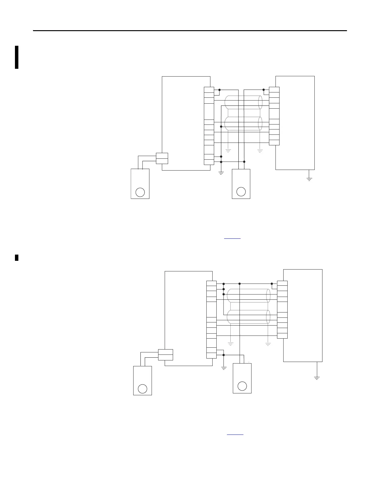
Kinetix 3 Drive and Micro830 Controller Wiring Examples
Figure 56 - Kinetix 3 Drive and 2080-LCxx-xxQBB Micro830 Controller
Figure 57 - Kinetix 3 Drive and 2080-LCxx-xxQBB Micro830 Controller
CLK+
CLK-
DIR+
DIR-
Enable
RST
1
2
49
12
25
14
3
7
+CM0
+CM1
O-00
O-03
O-06
O-07
-CM0
-CM1
+DC 24
-DC 24
1
2
––
+
+
2080-LC30-xxQBB
2080-LC50-xxQBB
Micro830 Controllers
Kinetix 3 Drive
24V
Power
Supply
24V
Power
Supply
Drive Enable (Pin 3) and Reset Drive (Pin 7) operates as sinking inputs when (Pin 1, 2)
connected to + of the Power Supply 2.
Drive Enable (Pin 3) and Reset Drive (Pin 7) operate as sourcing inputs when (Pin1,2)
connected to – of the Power Supply 2.
To help you configure Kinetix 3 drive parameters so the drive can communicate and be controlled
by a Micro830 or Micro850 controller, see publication CC-QS025
.
+CM0
+CM1
O-00
O-03
O-06
O-07
-CM0
-CM1
CLK+
CLK-
DIR+
DIR-
Enable
RST
1
2
49
12
25
14
3
7
1
–
+
2
–
–
+
+DC 24
-DC 24
2080-LC30-xxQVB
2080-LC50-xxQVB
Micro830 Controllers
Kinetix 3 Drive
24V
Power
Supply
24V
Power
Supply
Drive Enable (Pin 3) and Reset Drive (Pin 7) operates as sinking inputs when (Pin 1, 2)
connected to + of the Power Supply 2.
Drive Enable (Pin 3) and Reset Drive (Pin 7) operates as sourcing inputs when (Pin1,2)
connected to – of the Power Supply 2.
To help you configure Kinetix 3 drive parameters so the drive can communicate and be controlled
by a Micro830 or Micro850 controller, see publication CC-QS025
.
 Loading...


