Rockwell Automation Publication 2071-UM001E-EN-P - November 2013 127
Interconnect Diagrams Appendix A
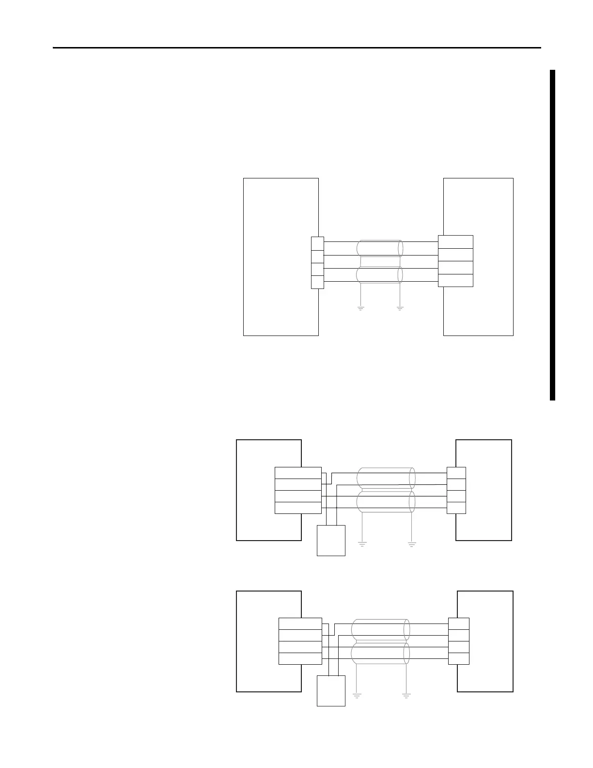
Kinetix 3 Drive and MicroLogix Controller Wiring Examples
The Kinetix 3 drive accepts unipolar or bipolar inputs.
Figure 54 - Kinetix 3 Drive Wiring Example to Analog Voltage Device
Commons must not be tied together. Use one control at a time. Choose either
velocity or current control.
Figure 55 - Kinetix 3 Drive Wiring for Pulse Train Output
20
19
22
21
COM
-10V…+10V
COM
-10V…+10V
VCMD +
VCMD -
ICMD +
ICMD -
Kinetix 3 Drive
I/O (IOD)
Connector
Analog Voltage
Device or PLC
Velocity
Current
V+ 24V DC
0/x
24 V DC V-
-
+
49
12
25
14
VDC 2
OUT x
OUT y
COM 2
+-
0/y
24V_PULS +
SIGN -
24V_SIGN +
PLUS -
24V_PULS
+
SIGN -
24V_SIGN +
PLUS -
49
12
25
14
MicroLogix 1400
Controller
Kinetix 3 Drive
Kinetix 3 Drive
MicroLogix 1100
Controller
MicroLogix 1400 Controller Sourcing Outputs
Kinetix 3 Drive Open Collector Inputs
MicroLogix 100 Controller Sourcing Outputs
Kinetix 3 Drive Open Collector Inputs
24 V DC
Supply
24 V DC
Supply
 Loading...


