32 Rockwell Automation Publication 2071-UM001E-EN-P - November 2013
Chapter 3 Kinetix 3 Drive Connector Data
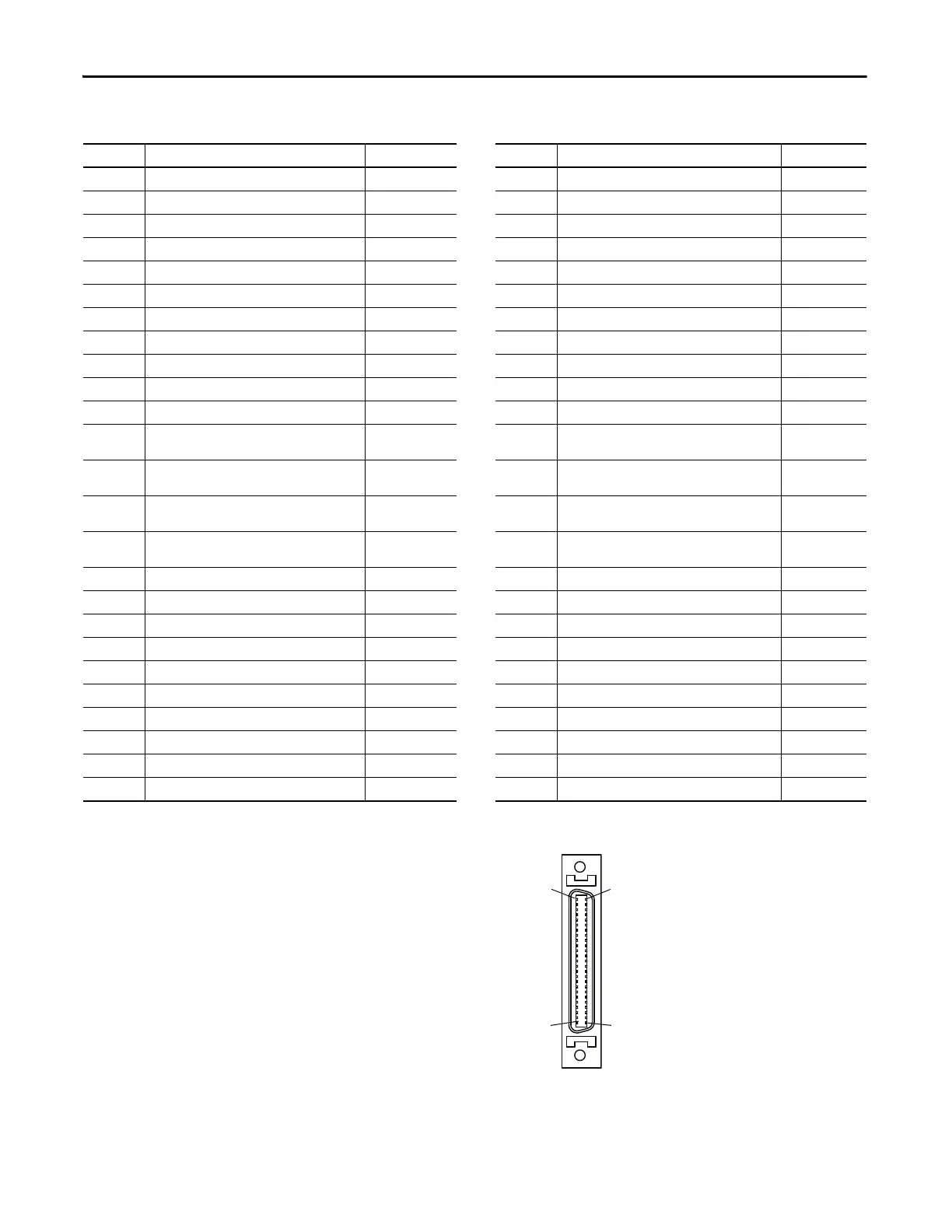
I/O (IOD) Connector Pinout
(1)
Figure 10 - Pin Orientation for 50-pin I/O (IOD) Connector
(1) The default settings for configurable digital inputs and outputs are shown in parenthesis.
IOD Pin Description Signal IOD Pin Description Signal
1 Digital input common 24V COM 26 Digital input 8 INPUT8
2 Digital input common 24V COM 27 Digital input 9 INPUT9
3 Digital input 1 (/SV-ON) INPUT1 28 Digital input 10 INPUT10
4 Digital input 2 (P-OT) INPUT2 29 Buffered encoder channel A+ AM+
5 Digital input 3 (N-OT) INPUT3 30 Buffered encoder channel A- AM-
6 Digital input 4 (/P-CON) INPUT4 31 Buffered encoder channel B+ BM+
7 Digital input 5 (A-RST) INPUT5 32 Buffered encoder channel B- BM-
8 Digital input 6 (/N-TL) INPUT6 33 Buffered encoder channel Z+ IM+
9 Digital input 7 (/P-TL) INPUT7 34 Buffered encoder channel Z- IM-
10 ESTOP (default: disable) ESTOP 35 Serial data of absolute encoder PS+
11 Follower input A+ PLUS + 36 Serial data of absolute encoder PS-
12 Follower input A- PLUS - 37
Alarm output 1
Digital output4
FAULT1
OUTPUT4
13 Follower input B+ SIGN + 38
Alarm output 2
Digital output5
FAULT2
OUTPUT5
14 Follower input B- SIGN - 39
Alarm output 3
Digital output6
FAULT3
OUTPUT6
15 High frequency pulse input A+ HF_PULS + 40
Alarm output
Digital outputs ground
FCOM
OUT COM
16 High frequency pulse input A- HF_PULS - 41 Digital output 1 + (P_COM+) OUTPUT1+
17 Encoder z-pulse Z-PULSE+ 42 Digital output 1 – (P_COM-) OUTPUT1-
18 Encoder z-pulse Z-PULSE- 43 Digital output 2 + (TG_ON+) OUTPUT2+
19 Velocity command input+ VCMD+ 44 Digital output 2 – (TG_ON-) OUTPUT2-
20 Velocity command input- VCMD- 45 Servo alarm + FAULT+
21 Current command input+ ICMD+ 46 Servo alarm - FAULT-
22 Current command input- ICMD- 47 Digital output 3 + (BK+) OUTPUT3+
23 High frequency pulse input B+ HF_SIGN + 48 Digital output 3 – (BK-) OUTPUT3-
24 High frequency pulse input B- HF_SIGN - 49 O/C for pulse of 24V level 24V_PULS +
25 O/C for sign of 24V level 24V_SIGN + 50 Reserved —
 Loading...


