Rockwell Automation Publication 2071-UM001E-EN-P - November 2013 69
Connect the Kinetix 3 Drive Chapter 4
Shunt Resistor
The B1 and B2 terminals are used to connect the shunt resistor. On the 2071-
AP4, 2071-AP8, 2071-A10, and 2071-A15 Kinetix 3 drives, the built-in shunt
resistor is pre-wired to B1 and B2 at the factory. On the 2071-AP0, 2071-AP1,
and 2071-AP2 Kinetix 3 drives, shunt resistors are not supported; no
terminations can be made to the B1 and B2 terminals for these drives.
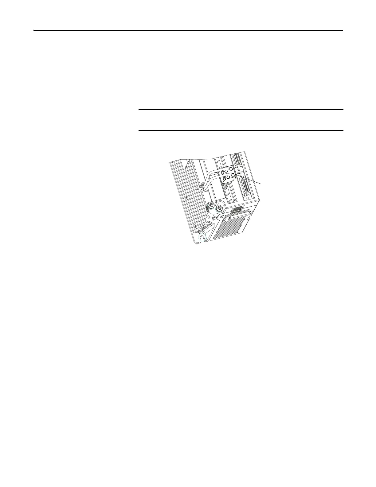
Figure 37 - Shunt Resistor (BC) Connector
The information supplied here is for reference only. There are no adjustments
or user serviceable parts associated with the shunt resistor.
Kinetix 3 Drive
Front view is shown.
Shunt Resistor (BC)
Connector
 Loading...


