68 Rockwell Automation Publication 2071-UM001E-EN-P - November 2013
Chapter 4 Connect the Kinetix 3 Drive
The cable shield clamp shown above is mounted to the subpanel. Ground and
secure the power cable in your system following instructions on page 70
.
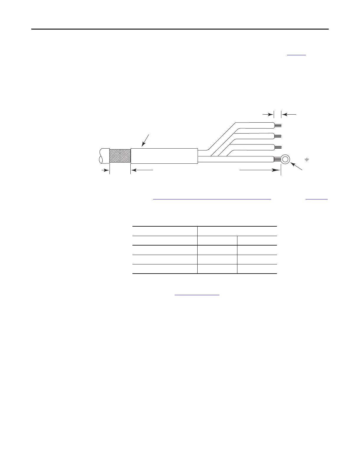
Cable shield and lead preparation is provided with most Allen-Bradley® cable
assemblies. Follow these guidelines if your motor power cable shield and wires
require preparation. The recommended wire size 2.5 mm
2
(14 AWG).
Figure 36 - Cable Shield and Lead Preparation
Refer to Kinetix 3 Drive/Rotary Motor Wiring Examples beginning on page 124
for interconnect diagrams.
Table 26 - Motor Power (MP) Connector
Green/yellow ground wire with ring lug is connected to the screw provided on
the drive. Shown Figure on page 70
.
W
V
U
Motor Power Cable
Exposed Braid
25.4 mm (1.0 in.)
Outer Insulation
As required to have ground clamp within 50…75 mm
(2…3 in.) of the drive.
7 mm (0.28 in.)
Attach a ring or fork lug to yellow and
green ground wire.
Servo Motor MP Connector
MP-Series, TL-Series MP Pin Signal
U / Brown 1 U
V / Black 2 V
W / Blue 3 W
 Loading...


