Rockwell Automation Publication 2071-UM001E-EN-P - November 2013 63
Connect the Kinetix 3 Drive Chapter 4
Wiring the Kinetix 3 Drive
Connectors
This section provides examples and wiring tables to assist you in making
connections to the Kinetix 3 drive.
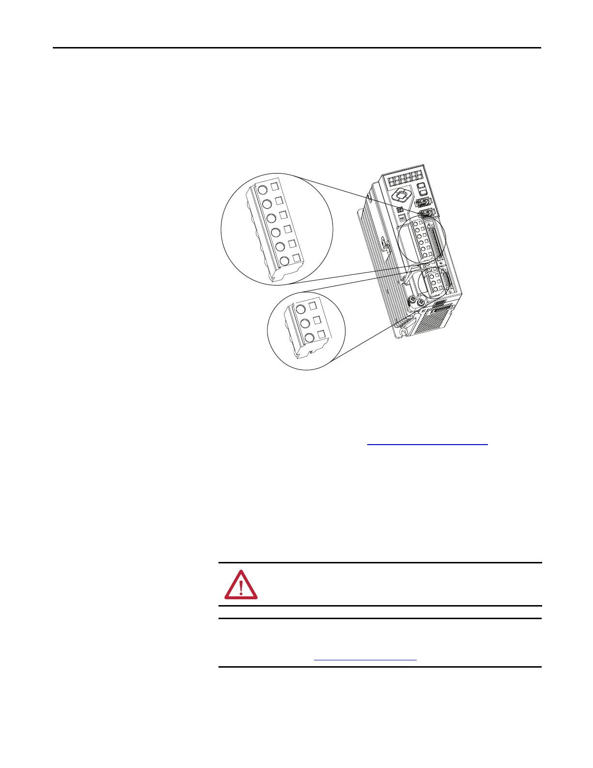
Wire the Input Power (IPD) and Motor Power (MP) Connectors
Figure 31 - Kinetix 3 Drive (IPD) and (MP) connector
The IPD is used for input power to the drive and the control circuits. The MP
connector is used to connect output power to the motor. Use 2.5 mm
2
(14 AWG)
wire for all connections. Connect ground to ground screw and torque to 1.25
N•m (11 lb•in) Follow procedure in Wiring Guidelines
on page 62.
Cable Shield Terminations
Factory-supplied motor power cables for MP-Series (Bulletin MPAS), TL-Series
(Bulletin TLY and TLAR), LDC-Series, and LDL-Series motors and actuators
are shielded. The braided cable shield must terminate near the drive during
installation. Remove small portion of the cable jacket to expose the shield braid
and clamp the exposed shield to the panel.
L1 L2 L3 L1C L2C DC-
U V W
L1
L2
L3
L1C
L2C
DC-
U
V
W
IPD
MP
ATTENTION: To avoid hazard of electrical shock, ensure shielded power cables
are grounded at a minimum of one point for safety.
For TL-Series motors, also connect the 152 mm (6.0 in.) termination wire to the
closest earth ground.
Refer to Pigtail Terminations on page 64 for more information.
 Loading...


