30 Rockwell Automation Publication 2071-UM001E-EN-P - November 2013
Chapter 3 Kinetix 3 Drive Connector Data
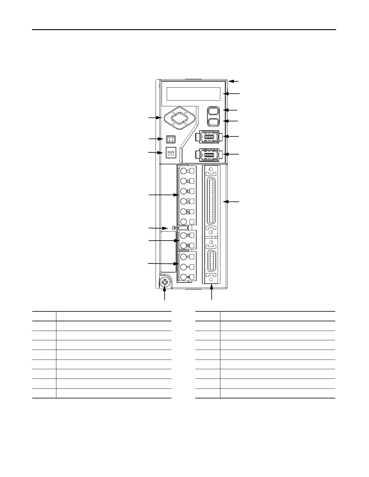
Kinetix 3 Drive Connectors
and Indicators
Although the physical size of the higher current drives is larger, the location of
the connectors and indicators is identical.
Figure 8 - Kinetix 3 Drive Connector and Indicators
Item Description Item Description
1 Left/right and up/down keys 9 Motor feedback (MF) connector
2 Analog output (A.out) connector 10 Input/output (IOD) connector
3 RS-485 communication termination switch 11 Serial interface (Comm0B) (down) port
4 Input power (IPD) connector 12 Serial interface (Comm0A) (up) port
5 Main power indicator 13 Enter key
6 Shunt resistor (BC) connector 14 Mode/set key
7 Motor power (MP) connector 15 7-segment status indicator
8Ground lug
(1)
16 2071-AP0 Kinetix 3 drive shown
(1) 2071-AP4 Kinetix 3 drives and larger have two ground screws.
I/O
Motor Feedback
DC -
15
1
5
14
13
9
10
4
6
7
12
2
3
8
11
16
 Loading...


