Rockwell Automation Publication 2071-UM001E-EN-P - November 2013 47
Kinetix 3 Drive Connector Data Chapter 3
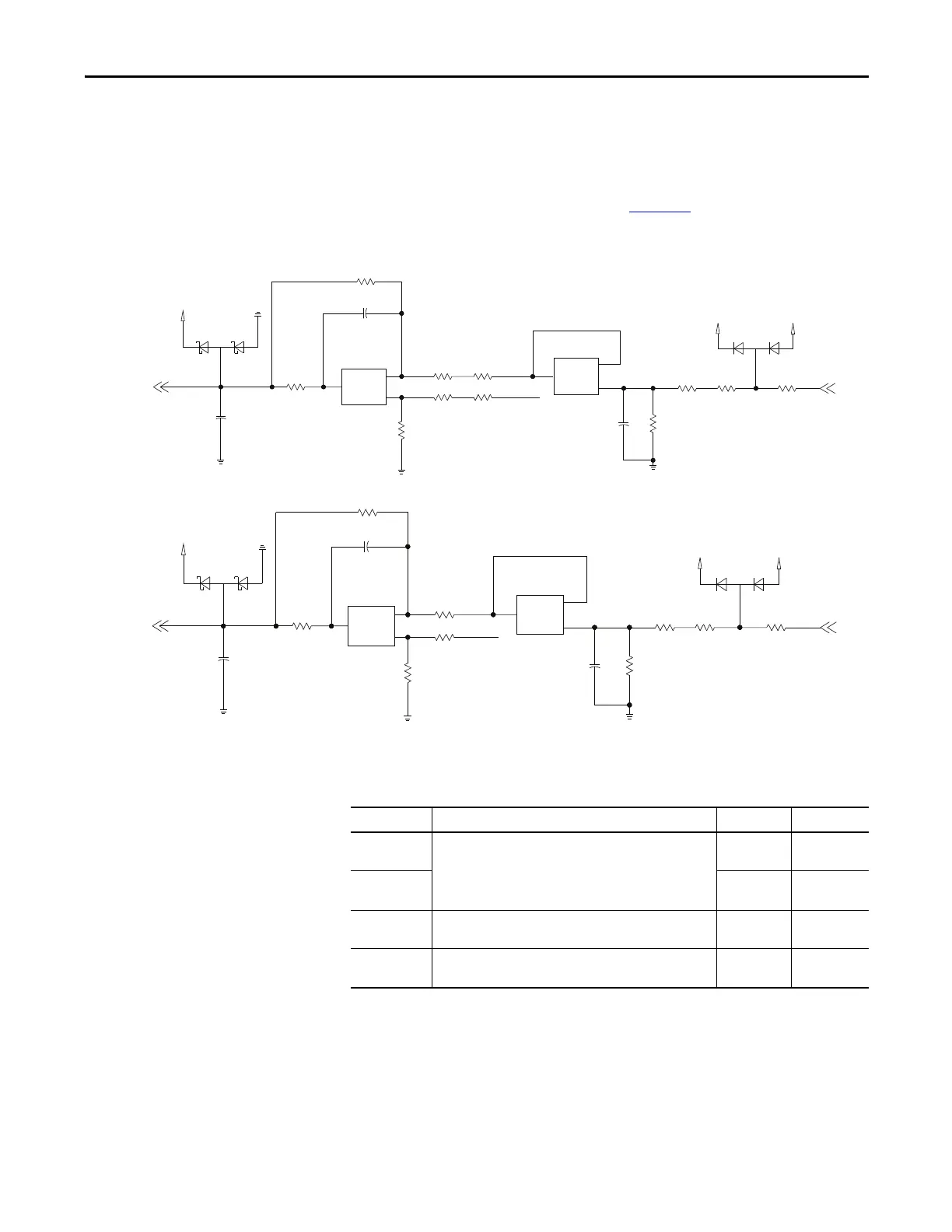
Analog Inputs
The Kinetix 3 drive has two single-ended analog inputs. One is dedicated as the
command input for Analog Velocity mode, and the second is dedicated as the
command input for Analog Current mode. Figure 21
shows the configuration of
the analog input.
Figure 21 - Analog Input Configuration
This table provides a description of the analog input specifications.
VCMD
-12V
+12V
GND
2.5V REF
GND
10 nF
GNDVCC
V_REF
GND
T_REF
GND
VCC GND
GND
2.5V REF
GND
+12V
-12V
ICMD
Parameter Description Min Max
VCMD
Resolution
Number of states that the input signal is divided into,
[2
(to the number of bits)
].
16 bits —
ICMD
Resolution
12 bits —
Input
Impedance
Open circuit impedance measured between the positive (+)
input and analog common.
10 kΩ —
Input Signal
Range
Voltage applied to the input. -10V +10V
 Loading...


