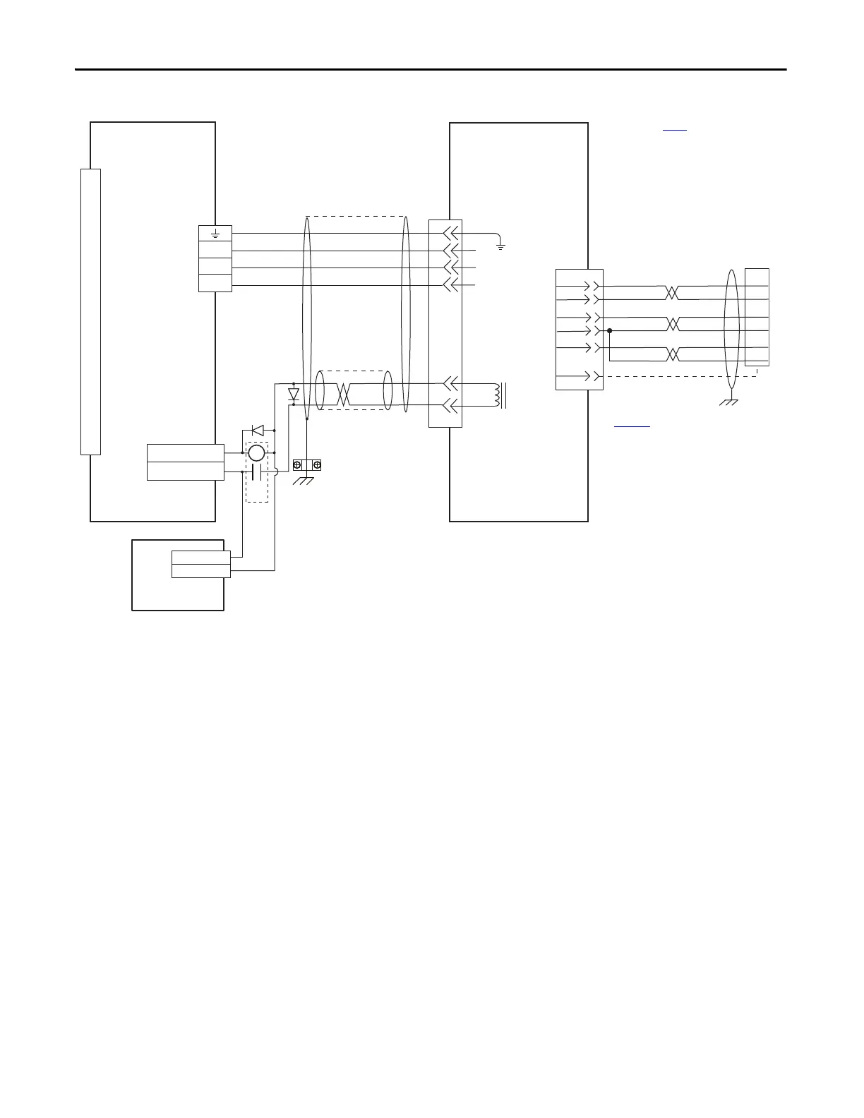
EasyManuals Logo

Rockwell Automation Allen-Bradley Kinetix 3 2071-AP8 User Manual

Rockwell Automation Allen-Bradley Kinetix 3 2071-AP8
134 pages
To Next Page IconTo Next Page
To Previous Page IconTo Previous Page
Page #126 background imageLoading...
Page #126 background image
126 Rockwell Automation Publication 2071-UM001E-EN-P - November 2013
Appendix A Interconnect Diagrams
Figure 53 - Kinetix 3 Drive (230V) Wiring Example with TL-Series (TLAR) Electric Cylinders
5
3
2
1
MBRK+
MBRK-
7
9
W
V
U
GND
0
1
2
3
4
5
6
7
8
9
10
11
12
13
14
15
16
17
18
19
20
48
47
GREEN/YELLOW
BLUE
BLACK
BROWN
BLACK
WHITE
W
V
U
+5VDC
ECOM
GRAY
WHT/GRAY
22
23
24
SHIELD
BAT+
BAT-
ORANGE
WHT/ORANGE
6
DATA+
DATA-
GREEN
WHT/GREEN
13
14
CR1
OUTPUT 3- (BK-)
OUTPUT 3+(BK+)
24V DC
24V DC COM
20
1
BAT+
BAT-
10
13
Motor Brake
Three-phase
Motor Power
Motor
Feedback
TLAR-Axxxx (230V)
Servo Motors with
High Resolution Feedback
2090-CFBM6DF-CBAAxx (flying-lead) or 2090-
CFBM6DD-CCAAxx (with drive-end connector)
Feedback Cable
Note 9
I/O (IOD)
Connector
Note 4
Motor Power
(MP) Connector
2071-Axx
Kinetix 3 Drive
Motor Feedback
(MF) Connector
2090-CPBM6DF-16AAxx
Motor Power and Brake Cable
Note 9, 10
Use 2090-CPWM6DF-16AAxx
cable for non-brake applications.
User Supplied
24V DC
Refer to table on page 122 for note information.
Cable
Shield
Clamp
Note 7
2071-TBMF
Motor Feedback
Breakout Board
with battery installed
Refer to Motor Feedback Breakout
Board Installation Instruction
Publication
2071-IN003
for proper grounding
technique.

Table of Contents

Questions and Answers:

Question and Answer IconNeed help?

Do you have a question about the Rockwell Automation Allen-Bradley Kinetix 3 2071-AP8 and is the answer not in the manual?

Rockwell Automation Allen-Bradley Kinetix 3 2071-AP8 Specifications

General IconGeneral
BrandRockwell Automation
ModelAllen-Bradley Kinetix 3 2071-AP8
CategoryServo Drives
LanguageEnglish

Related product manuals