38 Rockwell Automation Publication 2071-UM001E-EN-P - November 2013
Chapter 3 Kinetix 3 Drive Connector Data
Table 14 - Generic TTL Incremental Specifications
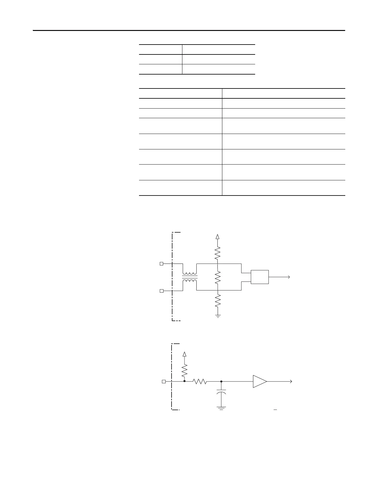
Figure 14 - Generic TTL Incremental, AM, BM and IM Signals
Figure 15 - Generic TTL Interface, S1, S2, or S3 Signals
State Resistance at TS
No Fault 1.6 kΩ
Fault 3.2 kΩ
Attribute Value
TTL incremental encoder support 5V, differential A quad B
Quadrature interpolation 4 counts/square wave period
Differential input voltage
(AM, BM, and IM)
0.5…2.5V
DC current draw
(AM, BM, and IM)
30 mA, max
Input signal frequency
(1)
(AM, BM, and IM)
(1) Propagation time differences in cables reduce the edge separation by 0.2 ns per meter. Both the propagation time differences and
the edge separation can reduce the maximum attainable input signal frequency.
3.5 MHz, max
Edge separation
(1)
(AM and BM)
50 ns min., between any two edges
Hall inputs
(S1, S2, and S3)
0.5…2.5V, Single-ended, TTL, open collector, or none
AM +
BM +
or IM+
AM -
BM -
or IM -
GND
4.7 kΩ
4.7
kΩ
220 kΩ
+5V
S1,
S2,
or S3
+5V
10 nF
1 k
Ω
4.7 k
Ω
 Loading...


