Rockwell Automation Publication 2198-UM001M-EN-P - November 2022 181
Appendix A Interconnect Diagrams
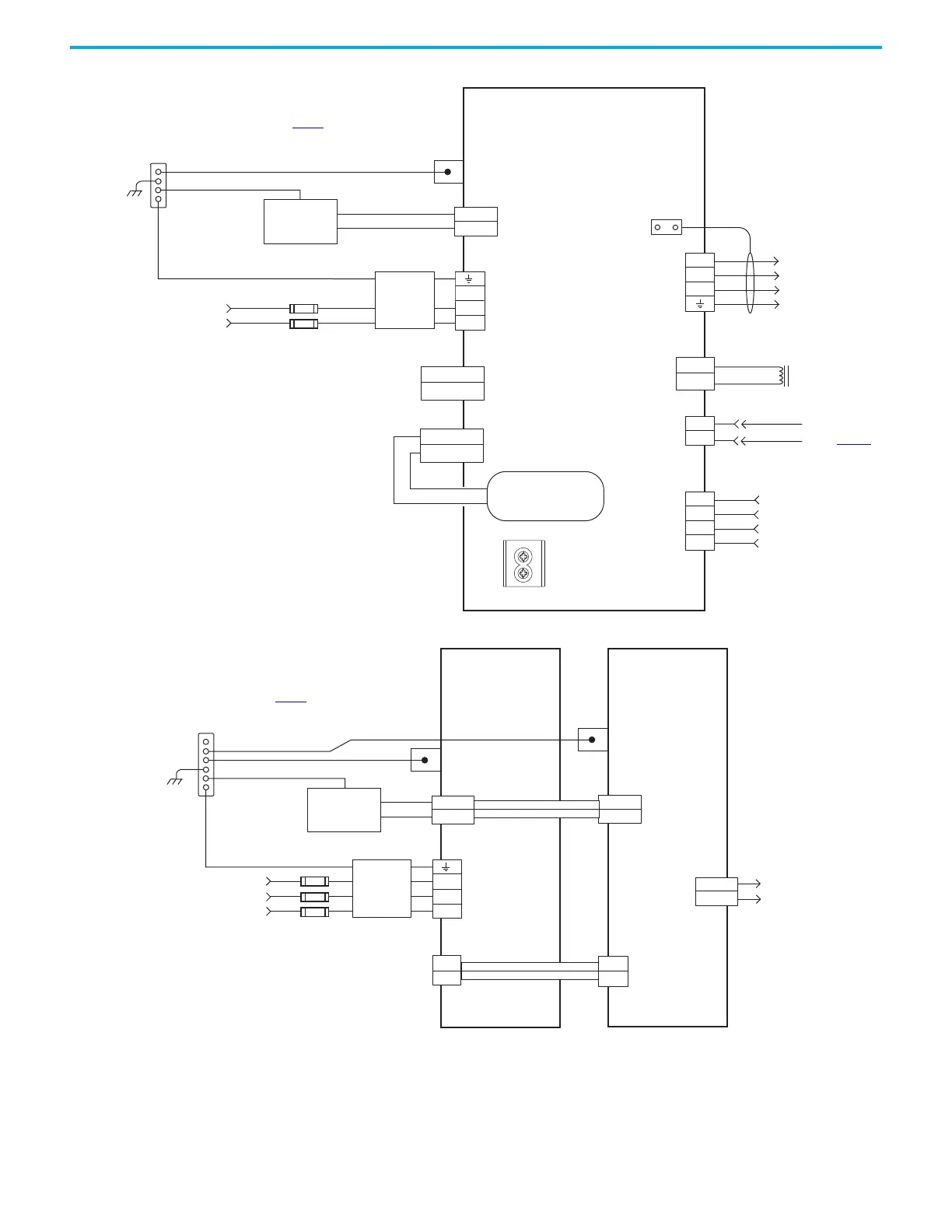
Figure 90 - Kinetix 5500 Drives Power Wiring (single-phase operation)
Figure 91 - Kinetix 5500 Capacitor Module
DATA +/EPWR+
DATA -/EPWR-
L3
L2
L1
2
1
MBRK -
MBRK +
U
V
W
2
1
D+
D-
IN1
COM
IN2
SHLD
1
2
4
3
2
1
4
3
2
1
1
2
3
4
MBRK -
MBRK +
DC+
SH
24V_COM
+24V
DC+
DC-
195…264V AC rms
Single-phase Input
Notes 1, 2
Bonded Cabinet Ground Bus *
Control Power
(CP) Connector
Mains AC Input
(IPD) Connector
* Indicates User Supplied Component
2198-H003-ERSx, 2198-H008-ERSx, or
2198-H015-ERSx
Kinetix 5500 Drives
Chassis
Note 4
Ground Screws
Note 9
Customer Supplied
+24V DC
Power Supply *
Motor Brake
(BC) Connector
Three-phase
Motor Power
Connections
Note 11
Motor Power
(MP) Connector
Cable Shield
Clamp
See table on page 179
for note information.
DC Bus (DC) Connector
(does not apply in single-
phase operation)
Shunt
(RC) Connector
Motor Feedback
(MF) Connector
Digital Input
(IOD) Connector
Motor Brake
Connections
Motor Feedback
Connections
(refer to Figure 97)
Registration and
Home Input
Connections
Circuit Protection *
Note 2
2198-DBxx-F
Three-phase
AC Line Filter
Note 3
Internal Shunt
Note 8
PE Ground
Note 6
Note 5
24V_COM
+24V
RELAY-
RELAY+
2
1
L3
L2
L1
4
3
2
1
24V_COM
+24V
2
1
DC+
DC-
DC+
DC-
Control Power
(CP) Connectors
DC Bus
(DC) Connectors
* Indicates User Supplied Component
2198-CAPMOD-1300
Capacitor Module
Module Status
(MS) Connector
Relay output to Logix 5000®
controller to monitor
capacitor module status.
Bonded Cabinet Ground Bus *
Chassis
Note 4
Customer Supplied
+24V DC
Power Supply *
See table on page 179
for note information.
2198-Hxxx-ERSx
Kinetix 5500 Drive
PE Ground
Note 6
2198-H0x0-ADP-IN
Busbar Connectors
PE Ground
Note 6
2198-DBxx-F
Three-phase
AC Line Filter
Note 3
195…264V AC rms or
324…528V AC rms
Three-phase Input
Notes 1, 2
Circuit Protection *
Note 2
2198-H0x0-DP-T
Busbar Connectors
Motor, digital input, and
shunt connections are
not shown for clarity.

 Loading...


