Rockwell Automation Publication 2198-UM001M-EN-P - November 2022 15
Chapter 1 Start
Drive Hardware and Input
Power Configurations
Typical Kinetix 5500 systems include single-phase and three-phase standalone
configurations, three-phase shared AC, shared AC/DC, shared DC, and shared
AC/DC hybrid configurations.
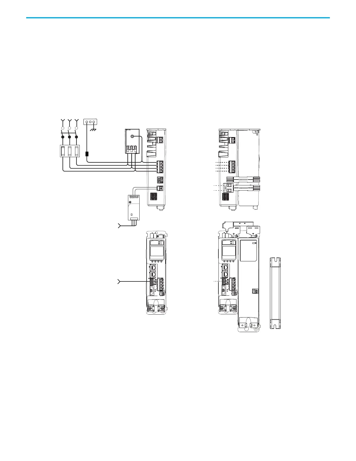
Standalone Configurations
In these examples, a single standalone drive is shown with and without the
Bulletin 2198 capacitor module.
Figure 1 - Typical Kinetix 5500 Standalone Installation
1606-XL
Power Supply
Input
Allen-Bradley
Single-phase or
Three-phase
Input Power
Line
Disconnect
Device
Input
Fusing
2198-Hxxx-ERSx Drive
(front view)
2097-Rx
Shunt Resistor
(optional component)
2198-Hxxx-ERSx Drive
(top view)
AC Input Power
Bonded Cabinet
Ground Bus
Mains AC and 24V input
wired to standard input
connectors.
2198-DBRxx-F
AC Line Filter
(can be required
for CE and UK)
Shared DC (DC common bus)
Shared 24V (control power input)
2198-Hxxx-ERSx Drive (top view) with
2198-CAPMOD-1300 Capacitor Module
2198-H0x0-x-x shared-bus
connection system for bus-
sharing configurations.
Mains AC input wired to
standard input connector.
Digital Inputs
to Sensors and Control String
1606-XLxxx
24V DC Control, Digital Inputs,
and Motor Brake Power
(customer-supplied)

 Loading...


