84 Rockwell Automation Publication 2198-UM001M-EN-P - November 2022
Chapter 5 Connect the Kinetix 5500 Drive System
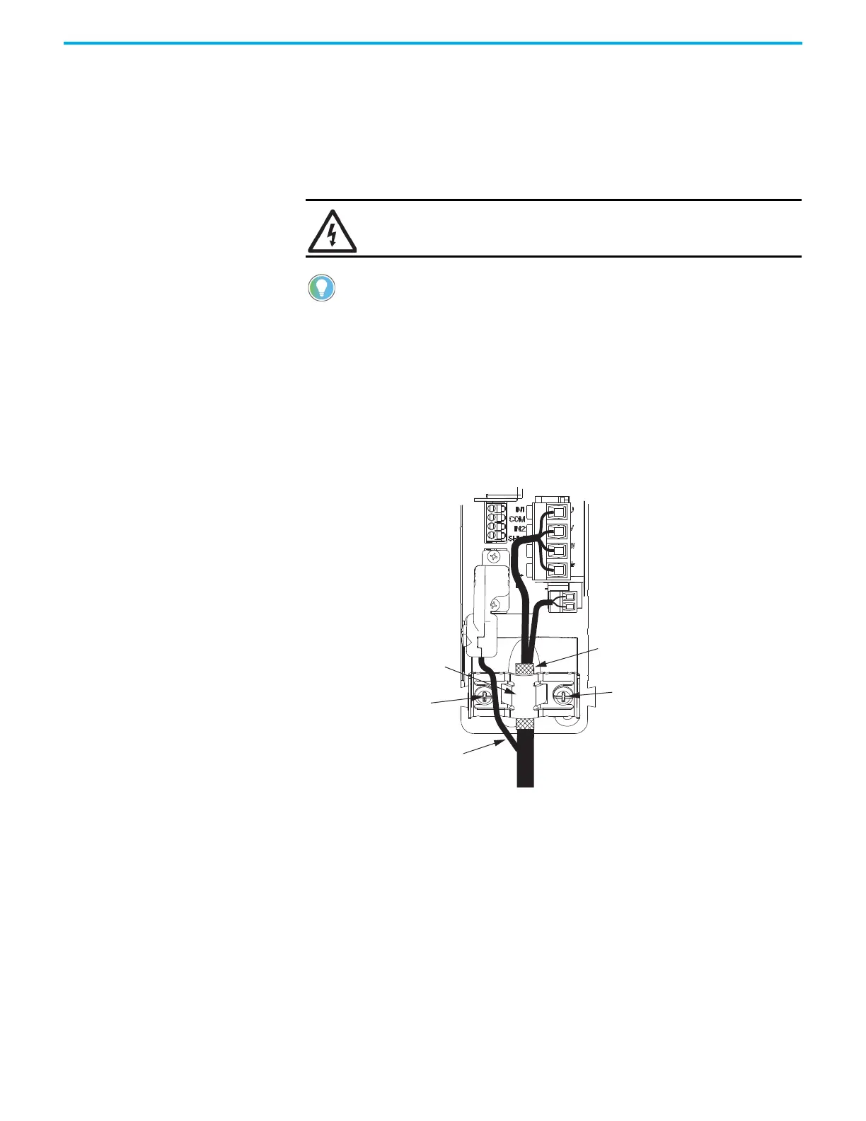
Apply the Single Motor-cable Shield Clamp
Factory-supplied Kinetix 2090 single motor cables are shielded, and the
braided cable shield must terminate at the drive during installation. A small
portion of the cable jacket has been removed to expose the shield braid. The
exposed area must be clamped (with the clamp provided) at the bottom front
of the drive.
This procedure assumes you have completed wiring your motor power, brake,
and feedback connectors and are ready to apply the cable shield clamp.
Follow these steps to apply the motor cable shield clamp.
1. Loosen the left-side (retention) clamp screw and remove the right-side
screw.
When the drive/motor combination calls for 18 AWG cable, the feedback
cable routes around the motor cable shield clamp.
SHOCK HAZARD: To avoid hazard of electrical shock, make sure that
shielded power cables are grounded according to recommendations.
Cables for Kinetix VP motors (catalog numbers 2090-CBxM1DF-18Axxx) do not
route the feedback bundle under the shield clamp. The 2090-CSxM1DG-18,
2090-CSxM1xx-14, and 2090-CSBM1xx-10 motor cables have the feedback
bundle within the cable shield braid.
Motor Cable
Shield Clamp
2198-KITCON-DSL
Motor Feedback
Connector Kit
Motor Power
(MP) Connector
Motor Brake
(BC) Connector
Exposed shield braid
under clamp.
Shield Clamp Screws (2)
2.0 N•m (17.7 lb•in), max
Kinetix 5500 Servo Drives,
Frame 1 or 2, Front View
(frame 1 is shown)
Feedback cable routed
around the shield clamp.
2090-CSxM1DF-18Axxx Single
Motor Cable
Retention Screw
(loosen, do not remove)
18 AWG Cable Installation

 Loading...


