Rockwell Automation Publication 2198-UM001M-EN-P - November 2022 79
Chapter 5 Connect the Kinetix 5500 Drive System
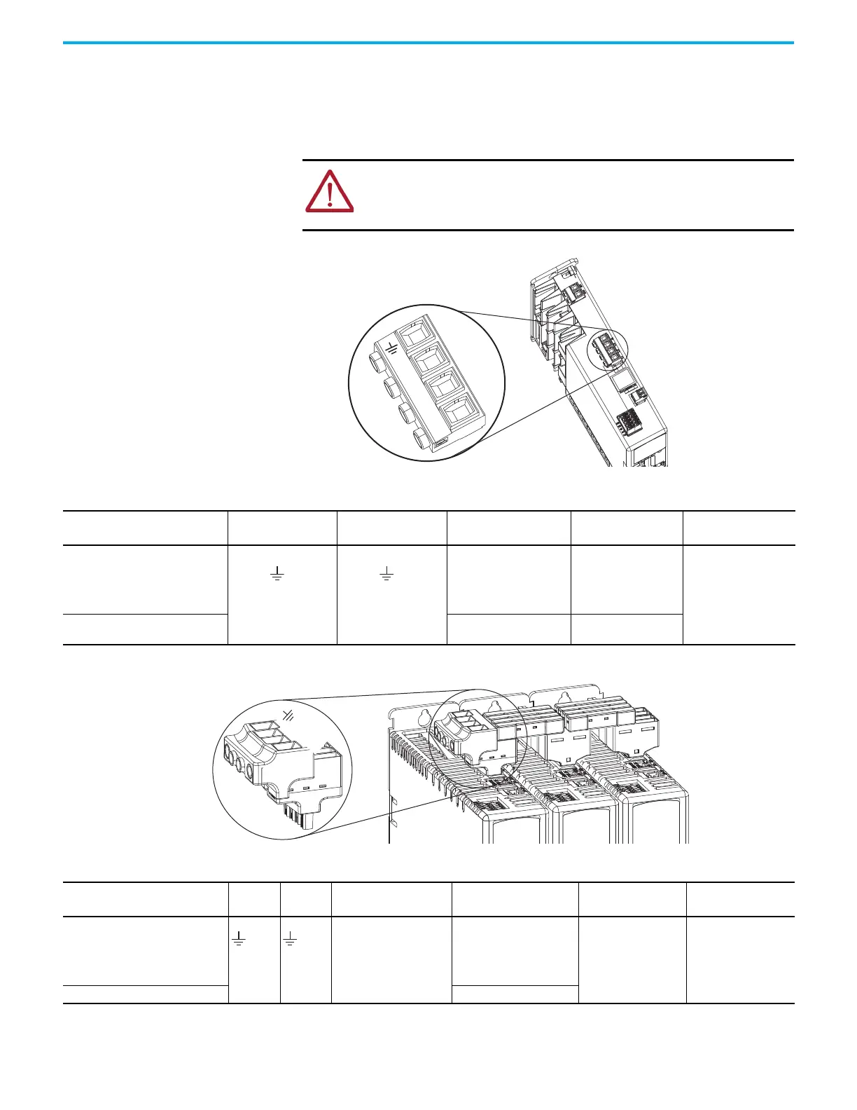
Wire the Input Power Connector
The input power (IPD) connector requires 195…528V AC (single-phase or three-
phase) for mains input power. The single-axis connector plug is included with
the drive, shared-bus connector kits are purchased separately.
Figure 47 - IPD Connector Wiring - Single Axis
Figure 48 - IPD Connector Wiring - Shared Bus
ATTENTION: Make sure that the input power connections are correct when
wiring the IPD connector plug or input wiring connector and that the plug/
connector is fully engaged in the drive connector. Incorrect wiring/polarity
or loose wiring can damage equipment or cause an explosion.
L3
L2
L1
Rem
ove
F
o
r DC
Bus Only
Kinetix 5500 Drive
Top View
Input Power (IPD)
Connector Plug
Table 39 - Single-axis IPD Connector Wiring Specifications
Kinetix 5500 Drive
Cat. No.
Pin Signal
Recommended Wire Size
mm
2
(AWG)
Strip Length
mm (in.)
Torque Value
N•m (lb•in)
2198-H003-ERSx
2198-H008-ERSx
2198-H015-ERSx
2198-H025-ERSx
2198-H040-ERSx
1.5…4
(16…12)
8.0 (0.31)
0.5…0.6
(4.4…5.3)
2198-H070-ERSx
1.5…6
(16…10)
10.0 (0.39)
Kinetix 5500 Drives
Top View
Mains AC Input
Wiring Connector
Table 40 - Shared Bus IPD Connector Wiring Specifications
Kinetix 5500 Drive
Cat. No.
Pin Signal
Input Current, Max
A rms
Recommended Wire Size
mm
2
(AWG)
Strip Length
mm (in.)
Torque Value
N•m (lb•in)
2198-H003-ERSx
2198-H008-ERSx
2198-H015-ERSx
2198-H025-ERSx
2198-H040-ERSx
52
13.3…3.3
(6…12)
11.0 (0.43)
1.7…1.8
(15.0…15.9)
2198-H070-ERSx 13.3 (6)

 Loading...


