92 Rockwell Automation Publication 2198-UM001M-EN-P - November 2022
Chapter 5 Connect the Kinetix 5500 Drive System
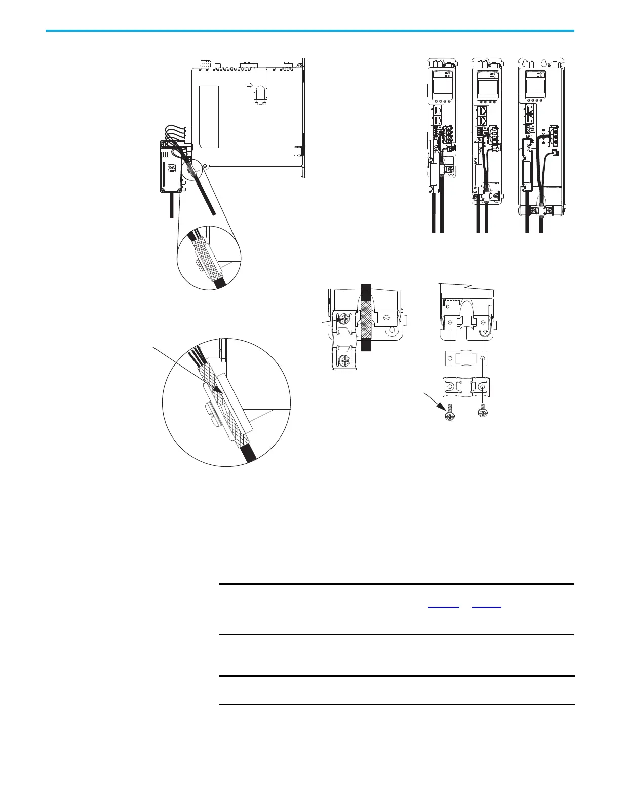
Figure 56 - Cable Clamp Attachment
(1) The clamp spacer is included with the Hiperface-to-DSL feedback converter kit, catalog number 2198-H2DCK.
Motor Feedback Connections
The feedback cable attaches to the 2198-H2DCK converter kit and is wired to
the 10-pin connector. Kinetix 2090 feedback cables require preparation to
make sure that the shield clamp attaches properly and conductors route
smoothly to the 10-pin connector terminals.
All current and legacy feedback cables that are listed below are compatible with
the 2198-H2DCK (series B or later) converter kit.
Clamp Compressed
Around Shield
(no spacer required)
Insert the clamp spacer when
the cable diameter is smaller
than the drive clamp alone.
Servo Drive
Clamp Spacer (if needed)
(1)
Shield Clamp
Clamp Screws
2.0 N•m (17.7 lb•in)
Service Loops
Frame 1
Servo Drive
Frame 2
Servo Drive
Frame 3
Servo Drive
Clamp Spacer Added
(small diameter cable)
Retention
Screw
Retention Screw
(loosen, do not remove)
Clamp features apply to all
frame sizes.
IMPORTANT When using the 2198-H2DCK feedback connector kit and Kinetix 2090
feedback cables that are listed in Table 50 or Table 51, the ambient
temperature for the Kinetix 5500 drive enclosure is derated to
0…40 °C (32…104 °F).
IMPORTANT Only Allen-Bradley motors and actuators with single-turn or multi-turn
high-resolution absolute encoders are compatible.

 Loading...


