46 Rockwell Automation Publication 2198-UM001M-EN-P - November 2022
Chapter 3 Mount the Kinetix 5500 Drive System
Determine Mounting Order Mount drives in order (left to right) according to power rating (highest to
lowest) starting with the highest power rating. If power rating is unknown,
position drives (highest to lowest) from left to right based on amp rating.
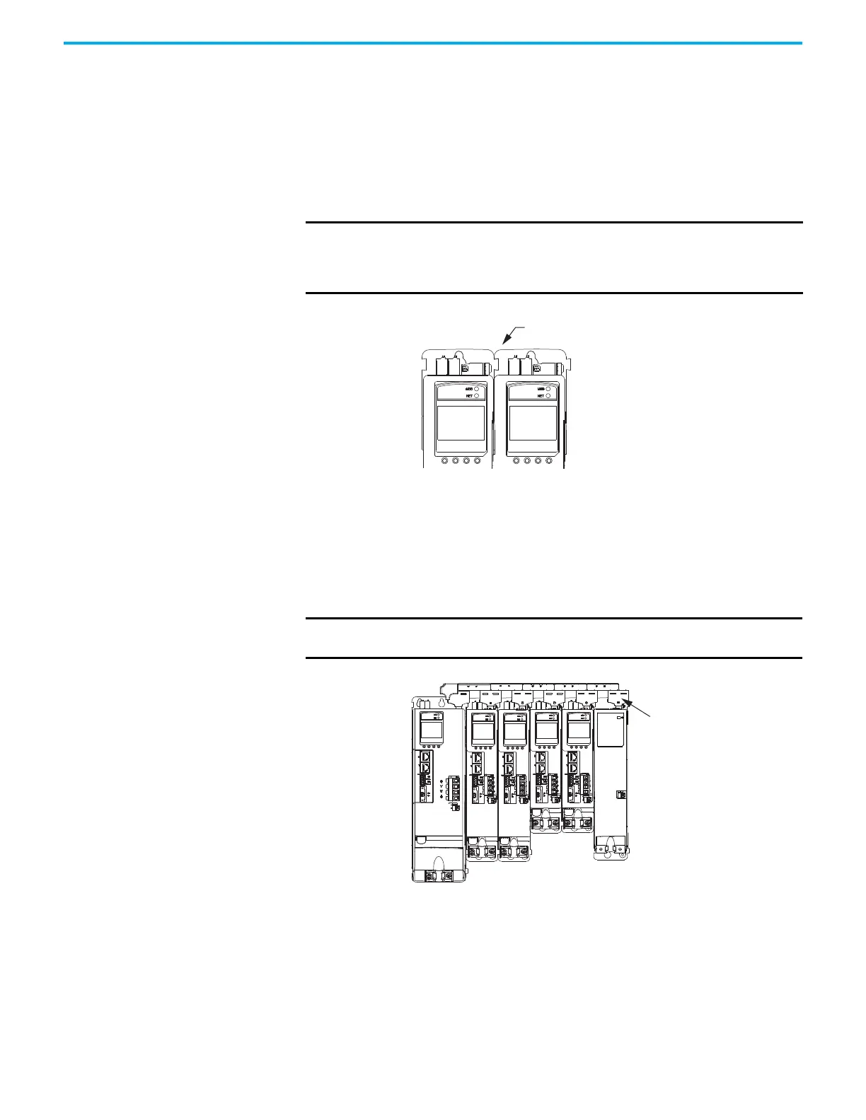
Zero-stack Tab and Cutout
Engaging the zero-stack tab and cutout from drive-to-drive makes efficient
use of panel space for installations with multiple drives.
Figure 21 - Zero-stack Tab and Cutout Example
For the zero-stack feature to engage properly when multiple frame sizes exist
in the drive system, the following conditions must be met:
• Frame 3 drives must mount to the left of frame 1 or 2 drives.
• Frame 2 drives must mount to the left of frame 1 drives.
Capacitor modules can mount to the right of any frame size, but are always
rightmost in any drive configuration.
Figure 22 - Shared-bus Connection System Example
IMPORTANT Engaging the zero-stack tab and cutout from drive-to-drive is required
for shared-bus multi-axis drive systems. This is done to make sure that
the drive connectors are spaced properly to accept the shared-bus
connection system.
IMPORTANT Mount drives in descending order, left to right, according to frame
size with capacitor modules always mounted on the far right.
2198-Hxxx-ERSx Drives
(front view)
Zero-stack Tab and Cutout Engaged
2198-Hxxx-ERSx Drive System
(front view)
Frame 3
Drive
Frame 2
Drives
Frame 1
Drives
2198-CAPMOD-1300 Capacitor
Module
Shared-bus Connection System
(required in shared-bus

 Loading...


