96 Rockwell Automation Publication 2198-UM001M-EN-P - November 2022
Chapter 5 Connect the Kinetix 5500 Drive System
Capacitor Module
Connections
Follow these guidelines when wiring the 2198-CAPMOD-1300 capacitor
module:
• Wire output (MS) connections to the Logix 5000® controller (optional).
• See Kinetix 5500 Capacitor Module
wiring example on page 181.
• See Kinetix 5500 Capacitor Module Status Indicators on page 147
for
troubleshooting the module status indicator and relay output.
• See the installation instructions provided with your Bulletin 2198
capacitor module, publication 2198-IN004
.
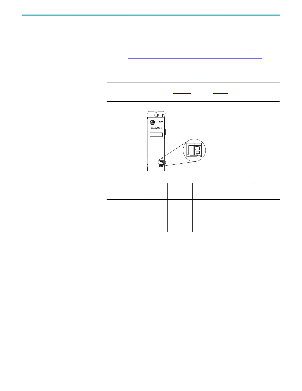
Figure 59 - MS Connector Wiring
IMPORTANT To improve system performance, run wires and cables in the wireways
as established in Chapter 2 starting on page 29. Connections to the DC-
bus must be made with the shared-bus connection system.
Module Status
(MS) Connector Plug
2198-CAPMOD-1300
Capacitor Module
Table 54 - Capacitor Module Connector Specifications
Connector
Description
Pin Signal
Recommended
Wire Size
mm
2
(AWG)
Strip Length
mm (in.)
Torque Value
N•m (lb•in)
Module Status
MS-1
MS-2
MS
MS
0.14…1.5
(28…16)
7.0 (0.28)
0.22…0.25
(1.9…2.2)
PELV/SELV
24V power (plug)
CP-1
CP-2
24V+
24V-
0.5…2.5
(20…14)
7.0 (0.28)
0.22…0.25
(1.9…2.2)
DC-bus power Busbar
DC-
DC+
—
(1)
—
(1)
(1) DC bus connections are always made from one drive module to another over the shared-bus connection system. These
terminals do not receive discrete wires.
—
(1)

 Loading...


