60 Rockwell Automation Publication 2198-UM001M-EN-P - November 2022
Chapter 4 Connector Data and Feature Descriptions
DC Bus and Shunt Resistor Connector Pinouts
Digital Inputs Connector Pinouts
The Kinetix 5500 drive has two configurable digital inputs and five
configurable functions to choose from in the Logix Designer application.
Digital input 1 can be configured as a dual-function (home/registration) input.
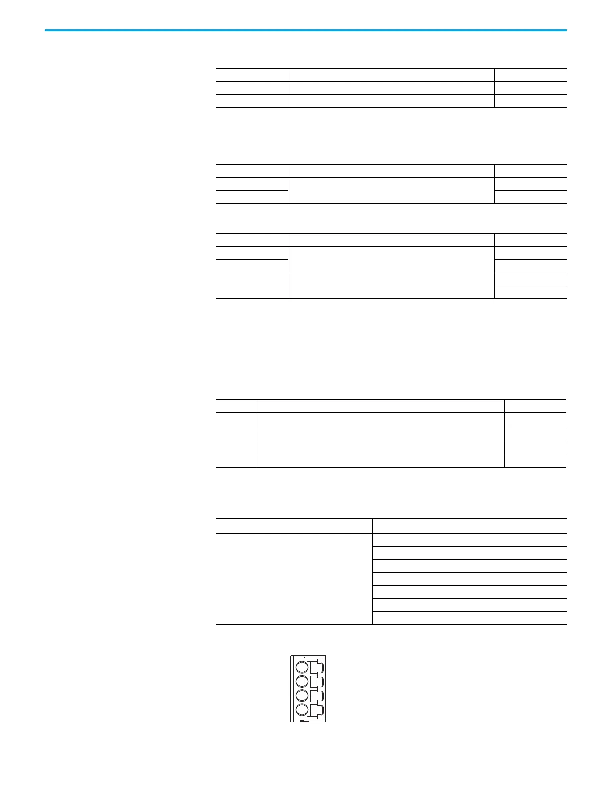
Figure 32 - Pin Orientation for Digital Inputs (IOD) Connector
Table 23 - 24V Input Power Connector
CP Pin Description Signal
1 24V power supply, customer supplied 24V+
2 24V common 24V-
Table 24 - DC Bus Power Connector
DC Pin Description Signal
1
DC bus connections
DC-
2DC+
Table 25 - Shunt Resistor Connector
RC Pin Description Signal
1
Shunt connections (frames 2 and 3)
DC+
2SH
1
Shunt connections (frame 1)
SH
2DC+
Table 26 - Digital Inputs Connector
IOD Pin Description Signal
1 24V current-sinking fast input #1. This is a dual-function input.
IN1
(1)
(1) This signal has dual-functionality. You can use IN1 (IOD-1) as Registration 1 or Home input when Home/Registration 1 is
configured.
2 I/O common for customer-supplied 24V supply. COM
3 24V current-sinking fast input #2. IN2
4 I/O cable shield termination point. SHLD
Table 27 - Configurable Functions
Default Configuration
(1)
(1) Studio 5000 Logix Designer,® version 27 or later, is required to change from the default configuration.
Description
Digital input1= Home/Registration 1
Digital input2 = Registration 2
Unassigned
Home
Registration 1
Registration 2
Positive overtravel
Negative overtravel
Home/Registration 1

 Loading...


