Rockwell Automation Publication 2198-UM001M-EN-P - November 2022 97
Chapter 5 Connect the Kinetix 5500 Drive System
External Passive-shunt
Resistor Connections
Follow these guidelines when wiring your 2097-Rx shunt resistor:
• See External Passive Shunt Resistor on page 43
for noise zone
considerations.
• See Shunt Resistor Wiring Example on page 184
.
• See the installation instructions provided with your Bulletin 2097 shunt
resistor, publication 2097-IN002
.
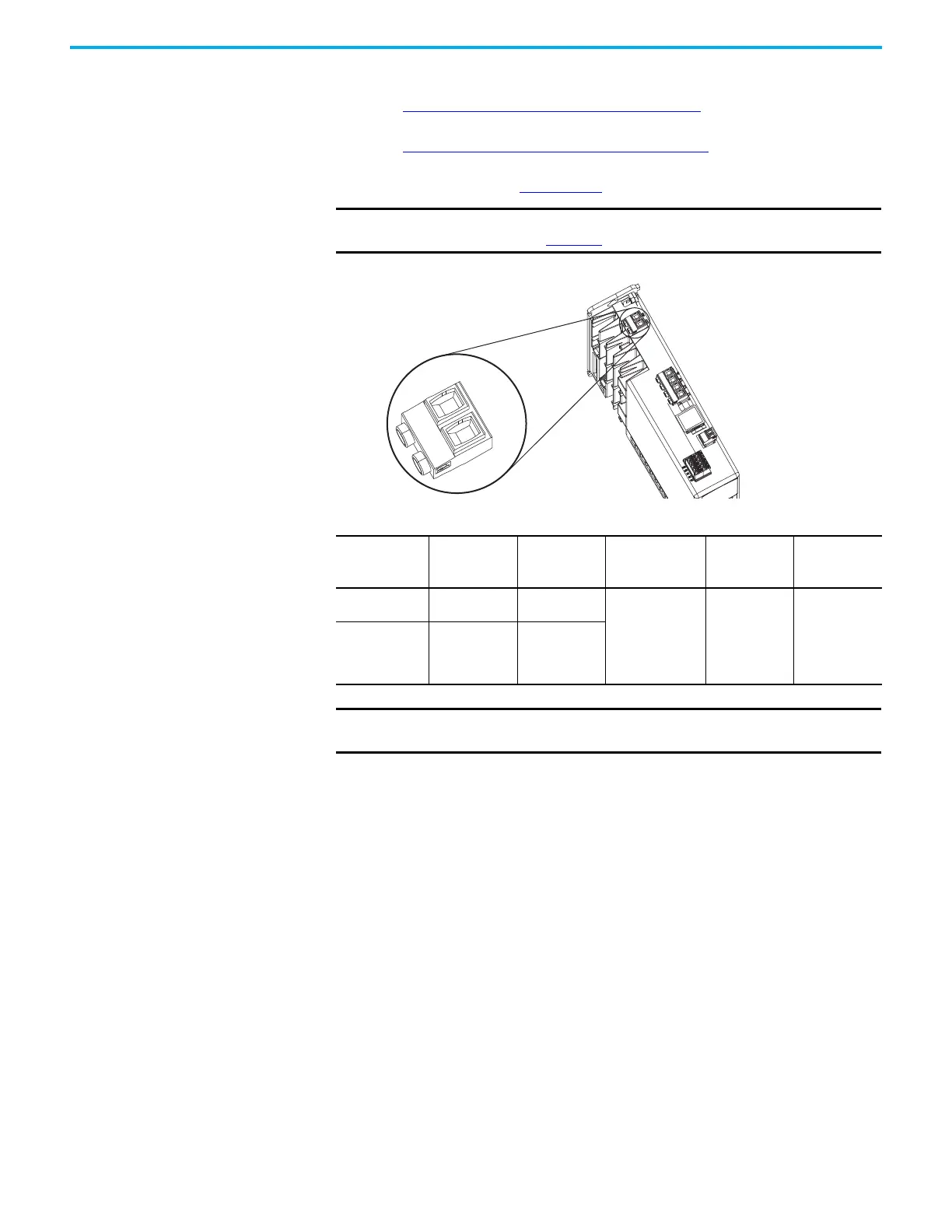
Figure 60 - RC Connector Wiring
IMPORTANT To improve system performance, run wires and cables in the wireways
as established in Chapter 2
.
Kinetix 5500 Drive
Top View
Table 55 - Shunt Resistor (RC) Connector Specifications
Drive Cat. No. Pin Signal
Recommended
Wire Size
mm
2
(AWG)
Strip Length
mm (in.)
Torque Value
N•m (lb•in)
2198-H003-ERSx
2198-H008-ERSx
RC-1
RC-2
SH
DC+
0.5…4.0
(20…12)
8.0 (0.31)
0.5…0.6
(4.4…5.3)
2198-H015-ERSx
2198-H025-ERSx
2198-H040-ERSx
2198-H070-ERSx
RC-1
RC-2
DC+
SH
IMPORTANT You must disconnect the internal shunt wires at the RC connector before
connecting the Bulletin 2097 shunt resistor wires.

 Loading...


