94 Rockwell Automation Publication 2198-UM001M-EN-P - November 2022
Chapter 5 Connect the Kinetix 5500 Drive System
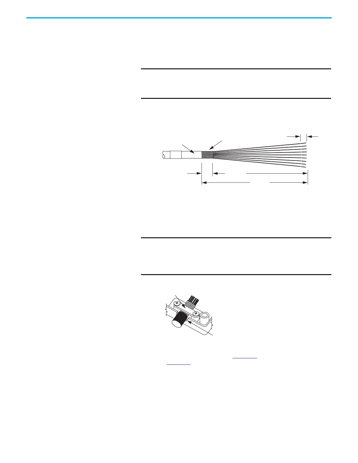
Motor Feedback Cable Preparation
Follow these steps to prepare feedback cables.
1. Remove 115 mm (4.5 in.) of cable jacket and 103 mm (4.0 in.) of cable
shield.
2. Determine the length for each of the 10 wires and trim as necessary.
3. Remove 5.0 mm (0.2 in.) of insulation from the end of each wire.
Apply the Converter Kit Shield Clamp
Follow these steps to apply the converter kit shield clamp.
1. Apply the shield clamp to the 12 mm (0.5 in.) of exposed cable shield to
achieve a high-frequency bond between the shield braid and clamp.
Apply 0.30 N•m (2.6 lb•in) torque to each screw.
2. Route and insert each wire to its assigned terminal.
Include a service loop, as shown in Figure 58
, and refer to the connector
pinout in Figure 57.
3. Tighten each terminal screw.
Apply 0.22…0.25 N•m (1.9…2.2 lb•in) torque to each screw.
4. Gently pull on each wire to make sure it does not come out of its
terminal; reinsert and tighten any loose wires.
5. Attach the tie wrap for added stress relief.
IMPORTANT This length of wire is required to provide a service loop for the
longest wires terminated at the 10-pin connector. However, most
wires must be trimmed shorter, depending on the terminal they
are assigned to.
12.0 (0.5)
5.0 (0.2)
115 (4.5)
103 (4.0)
Cable Jacket
Cable Shield
Dimensions are in mm (in.)
IMPORTANT Cable preparation and positioning that provides a high-
frequency bond between the shield braid and clamp is
required to optimize system performance.
Also, make sure that the cable is positioned where the cover
clamps onto the jacket for added stress relief.
Shield Clamp
Cable Positioned Where Cover Clamps
Onto the Cable Jacket

 Loading...


