Rockwell Automation Publication 2198-UM001M-EN-P - November 2022 43
Chapter 2 Plan the Kinetix 5500 Drive System Installation
External Passive Shunt Resistor
Observe these guidelines when mounting your Bulletin 2097 external
passive-shunt resistor outside of the enclosure:
• Mount shunt resistor and wiring in the very dirty zone or in an external
shielded enclosure.
• Mount resistors in a shielded and ventilated enclosure outside of the
cabinet.
• Keep unshielded wiring as short as possible. Keep shunt wiring as flat to
the cabinet as possible.
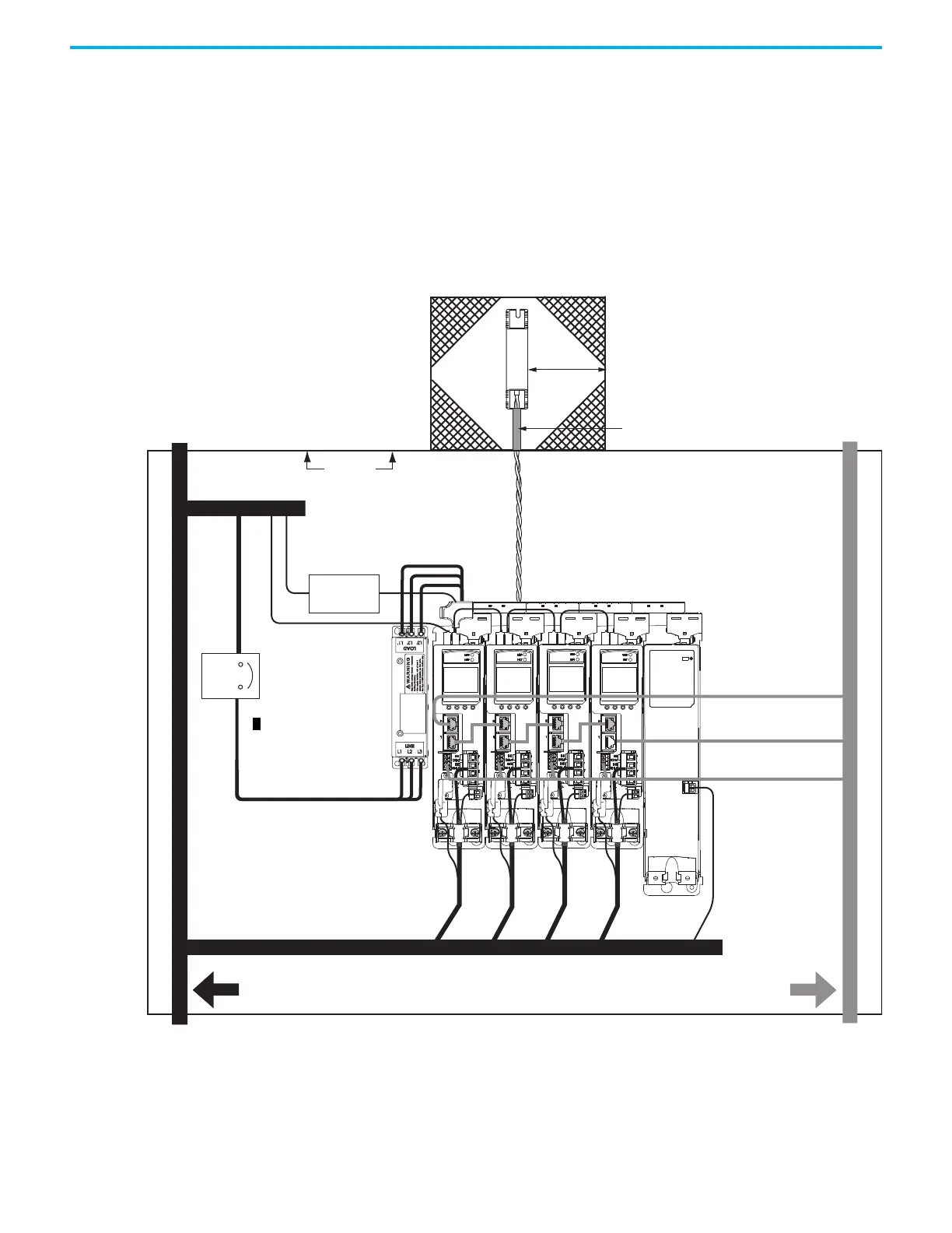
Figure 19 - External Shunt Resistor Outside the Enclosure
Dirty Wireway
Clean Wireway
Single Motor Cable
Very Dirty Connections Segregated
(not in wireway)
Customer-supplied
Metal Enclosure
150 mm (6.0 in.)
clearance (min) on all four
sides of the shunt resistor.
Enclosure
Metal Conduit (where required
by local code)
No sensitive
equipment within
150 mm (6.0 in.).
Shunt Power Wiring Methods:
Twisted pair in conduit (first choice).
Twisted pair, two twists per foot (min) (second choice).
Circuit
Breaker
Route single motor cables
in shielded cable.
Route registration and communication
signals in shielded cables.
Kinetix 5500 Servo Drive System
24V DC
Power Supply
AC Line Filter
(can be required for
CE and UK)
Module Status
Safety Cable
(2198-Hxxx-ERS drives only)
Ethernet and I/O Cables

 Loading...


