Rockwell Automation Publication 2198-UM001M-EN-P - November 2022 85
Chapter 5 Connect the Kinetix 5500 Drive System
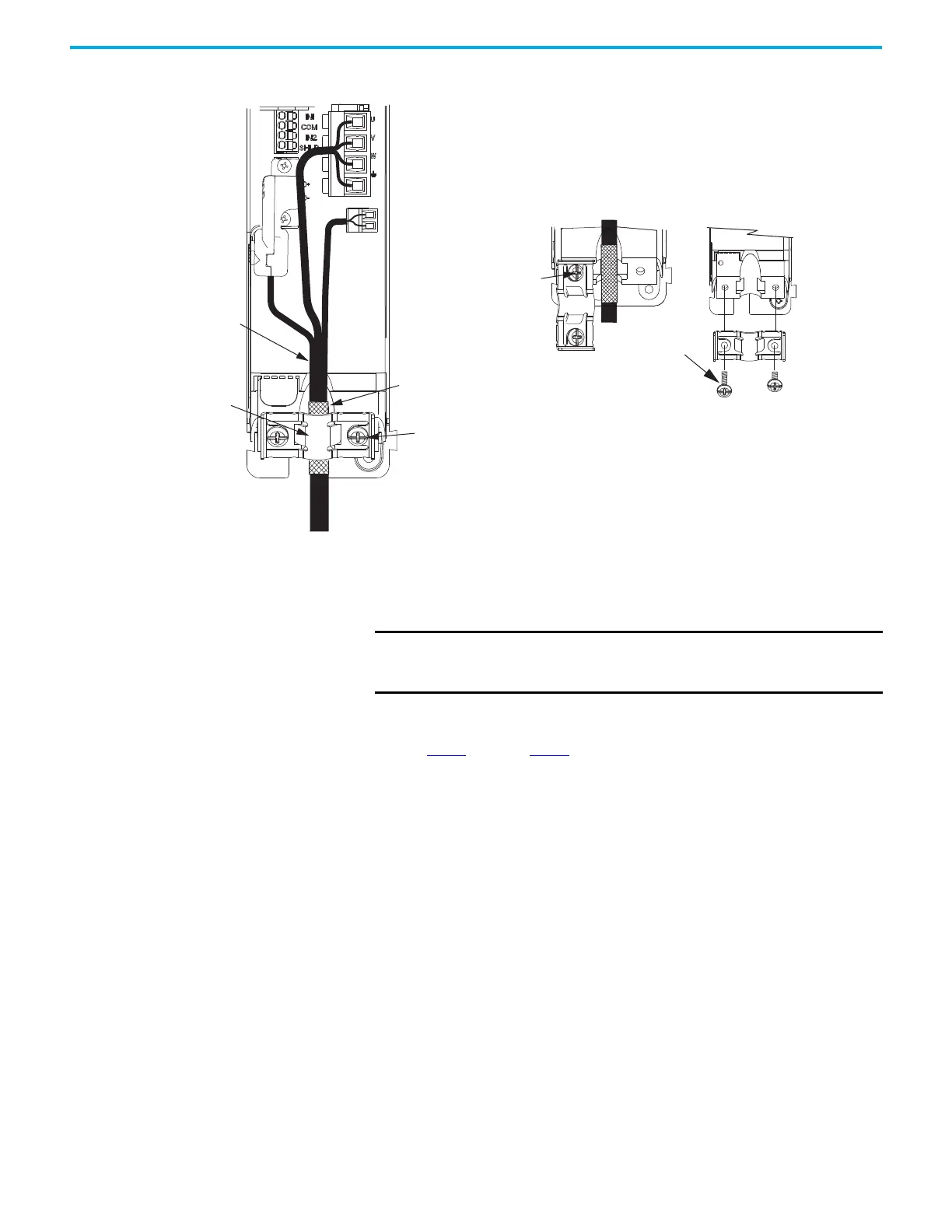
When the drive/motor combination calls for 14 AWG or 10 AWG cable,
the feedback cable routes along with the power and brake wiring.
2. Position the exposed portion of the cable shield directly in line with the
clamp.
3. Tighten each screw a few turns at a time until the maximum torque value
of 2.0 N•m (17.7 lb•in) is achieved.
4. Repeat step 1
through step 3 for each drive in multi-axis configurations.
Motor Cable
Shield Clamp
Motor Power
(MP) Connector
Motor Brake
(BC) Connector
Exposed shield braid
under clamp.
Shield Clamp Screws (2)
Feedback cable routed
within the shield braid.
Kinetix 5500 Servo Drives,
Frame 2 or 3, Front View
(frame 2 is shown)
2198-KITCON-DSL
Motor Feedback
Connector Kit
Retention Screw
(loosen, do not remove)
Clamp features apply to all
frame sizes.
Torque clamp screws to
2.0 N•m (17.7 lb•in), max
2090-CSxM1Dx-14xxxx
Single Motor Cable
Servo Drive
Shield Clamp
Clamp Screws
2.0 N•m (17.7 lb•in)
Retention
Screw
14 AWG and 10 AWG Cable Installation Example
IMPORTANT Loosen the retention screw, if needed, until you can start
threading both clamp screws with the cable shield under the
clamp.

 Loading...


