Rockwell Automation Publication 2198-UM001M-EN-P - November 2022 53
Chapter 3 Mount the Kinetix 5500 Drive System
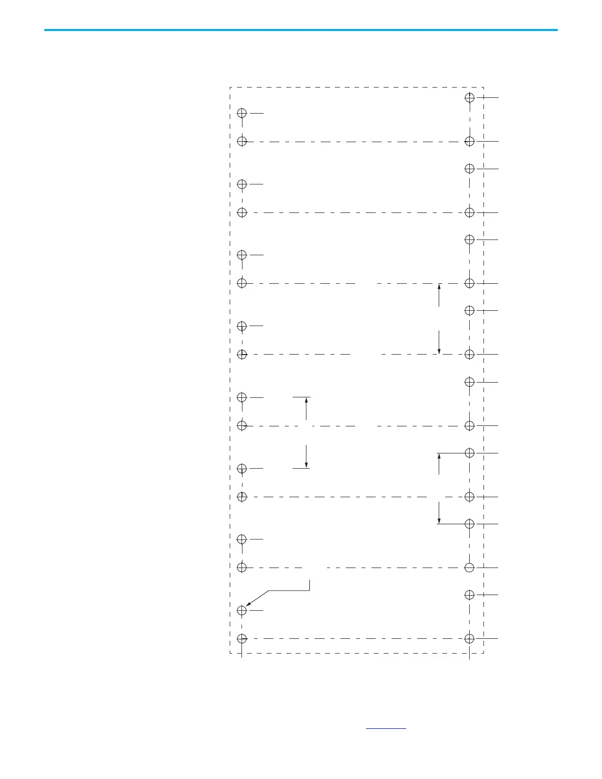
This hole pattern applies when all drives in the system are frame 3 drives.
There is 85.20 mm (3.35 in.) between mounting holes, as shown.
Figure 27 - Frame 3 Hole Pattern
This hole pattern applies when transitioning from frame 3 drives to frame 1
drives. To mount additional frame 1 drives to the right of Axis 2 in this figure,
refer to the frame 1 hole pattern in Figure 25
.
273.70
0
52.50
85.20
137.70
0
170.40
222.90
255.60
308.10
340.80
393.30
426.0
478.50
511.20
563.70
596.40
648.90
Axis 1 Axis 2 Axis 3 Axis 4
Axis 5 Axis 6 Axis 7 Axis 8
32x
ØM4 (#8-32)
34.00
119.20
204.40
289.60
374.80
460.0
545.20
630.40
85.20
85.20
85.20
Hole spacing is measured in millimeters and not
converted to inches to avoid errors due to rounding.

 Loading...


