Serial Communications
8-13
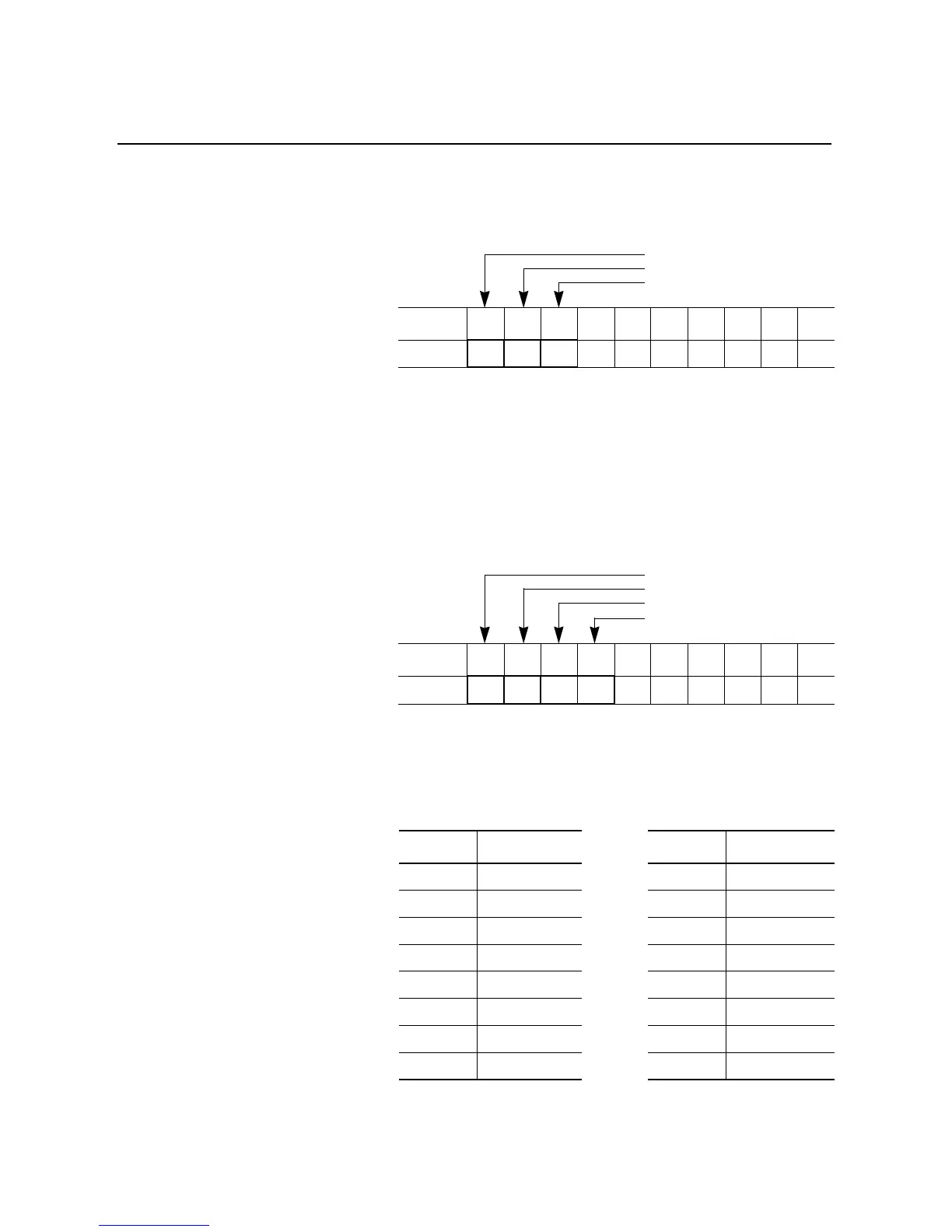
BT Control Buffer Layout – The following table maps integer files
starting at N10:0 with the associated M0 file location as defined in the
sample ladder logic program that follows.
BT Control Datafile
①
BT logical address format: logical rack/group/slot (slot is always “0” for the 1203-GD1)
Logical address examples Logical Rack
0
, Group
0
, Slot
0
=
0
Logical Rack
2
, Group
4
, Slot
0
=
240
②
This word is set by the ladder logic program. Refer to the 1747-SN scanner manual for Control Flag
Definitions.
BTW Datafile Format – A four-word data file is required to
accomplish a “Continuous Parameter Value Read.” For the example
that follows, the BTW Datafile will begin at address N10:10.
BTW Datafile
①
This is a fixed value, associated with the “Continuous Parameter Value Read” function.
Data Path for the BTW – Rung 2:6 of the sample ladder logic
program that follows executes a COP instruction to the M0 file to load
the necessary data for the BTW.
Address0123456789
N10:0
②
64 0
Address0123456789
N10:10 4 1
①
11 1
Address 0 1 2 3 4 5 6 7 8 9 Address 0 1 2 3 4 5 6 7 8 9
N10:0
£
M0:1.100
N10:10
£
M0:1.110
N10:20
£
M0:1.120
N10:30
£
M0:1.130
N10:40
£
M0:1.140
N10:50
£
M0:1.150
N10:60
£
M0:1.160
N10:70
£
M0:1.170
Control Flags
BT Length
BT Logical Address
①
Message Length
PLC Decimal Value
Number of Parameter Values to Read
Starting Parameter Number

 Loading...


