Date Code 20010731 Breaker Logic 3-43
SEL-352-1, -2 Instruction Manual
Set the UBPF bit to assert an alarm or trip the breaker. Table 3.3 gives the amount of tapped
load in percent of total load that may exist between the relay location and the open conductor for
the relay to still detect the open conductor. The 50LD setting determines the amount of total
load necessary for the logic to work. For a single open conductor condition, if 50LD is set to 0.1
A, phase current must be greater than the values in the secondary current column.
Table 3.3: Open Conductor Detection Specifications
46UB Setting % Tapped Load Secondary Current (Amps)*
8 25 0.13/phase
16 12 0.14/phase
32 5 0.18/phase
64 3 0.23/phase
*On a 5 A basis. Divide values by 5 for 1 A relay.
LOSS-OF-DIELECTRIC DETECTION
Application Description
Many breakers use pressurized air or gas as a dielectric and to help interrupt the electrical arc
when tripping. If the amount of gas pressure is insufficient, the breaker may fail. Many breakers
that rely on air or gas for such applications have pressure monitors, so the breaker will not
attempt to operate under possible failure conditions. These pressure monitors can be connected
to the SEL-352 Relay for sophisticated monitoring, reporting, and breaker failure tripping.
Operating Characteristic
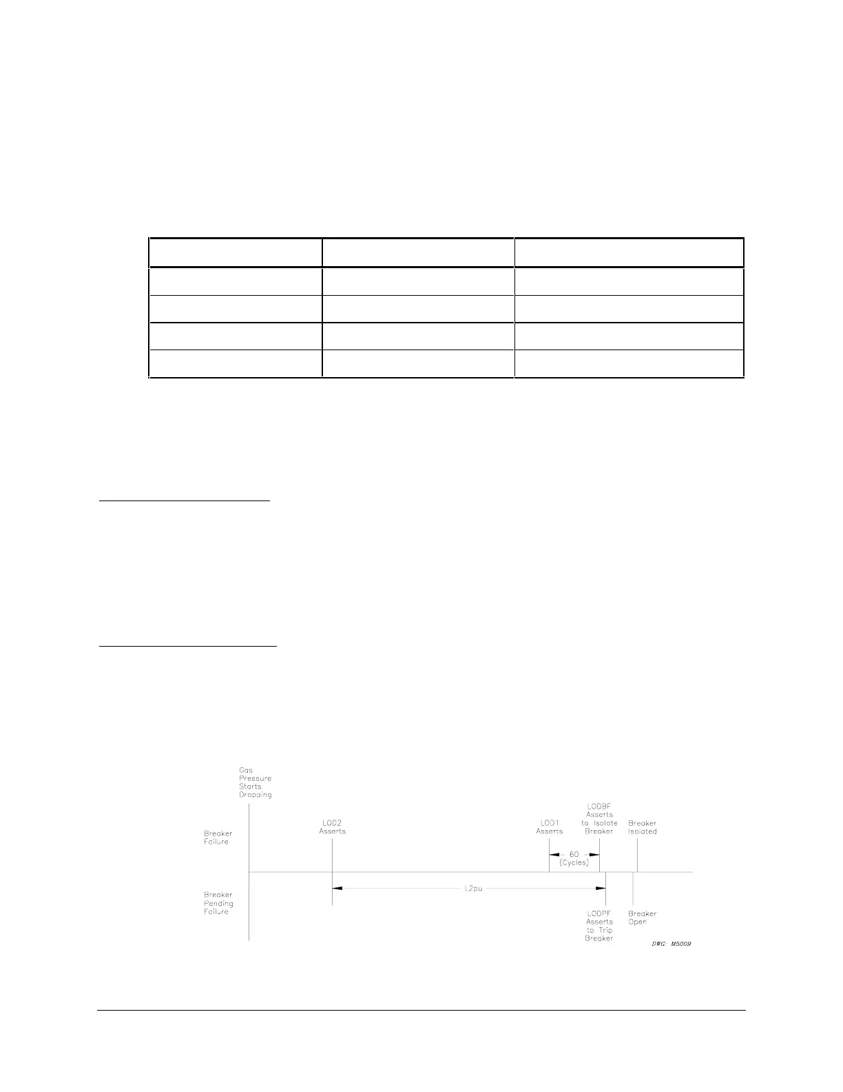
The output of the loss-of-dielectric detection logic is a pending failure indication, LODPF, and a
failure condition indication, LODBF. Use the pending failure output to trip the breaker before
the gas pressure decreases to a level where the breaker could fail. Use the failure condition to
trip the lockout relay and isolate the breaker. Section 4: Close Logic provides the logic diagram
for this logic. Refer to Figure 3.25 for a timing diagram of the loss-of-dielectric detection logic.
Figure 3.25: Loss-of-Dielectric Detection Timing



 To Next Page