Date Code 20010731 Installation 2-13
SEL-352-1, -2 Instruction Manual
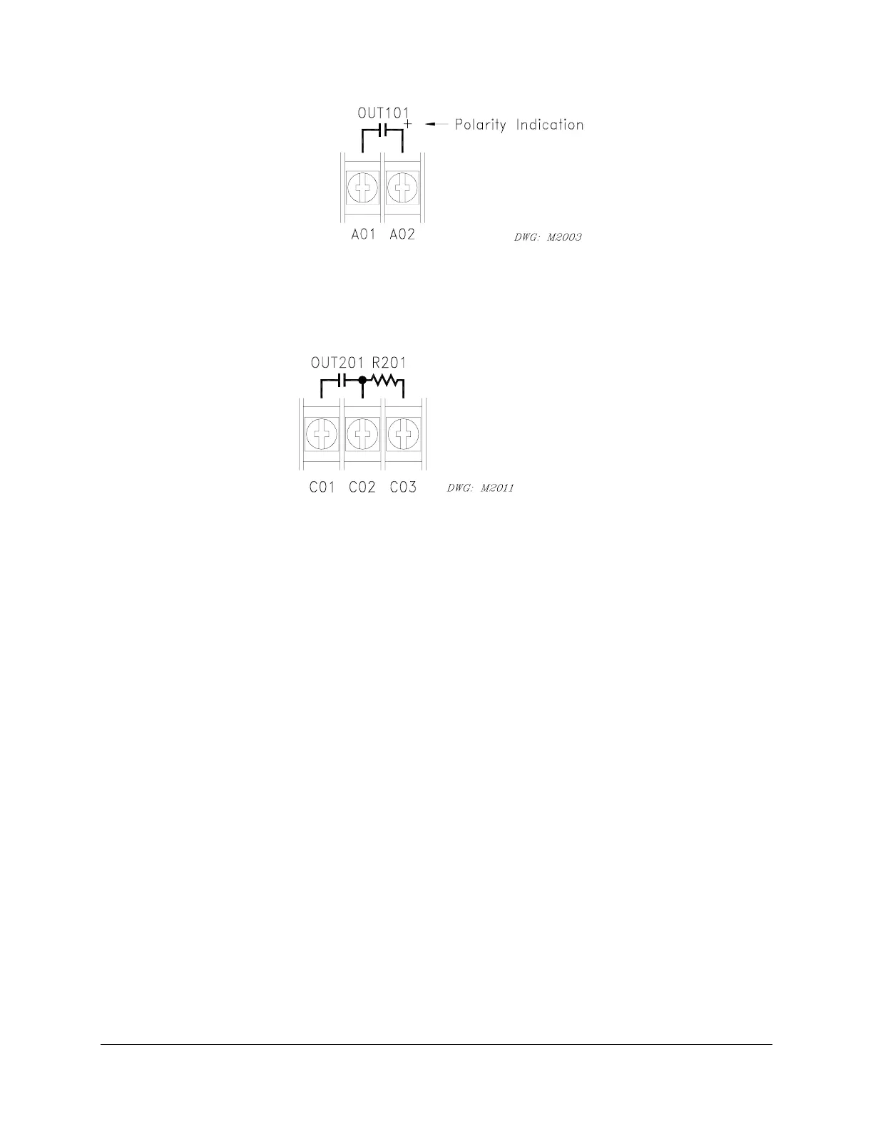
Figure 2.11: High Current Interrupting Output Contact Representation
Fast High Current Interrupting dry output contacts that are not polarity dependent are
represented by Figure 2.12.
Figure 2.12: Fast High Current Interrupting Output Contact Representation
(Note: Some early model versions did not show the resistor)
Communications Port
Refer to Table 2.1 for a list of cables that you can purchase from SEL for various communication
applications. Refer to Section 8: Serial Port Communications and Commands for detailed
cable diagrams for selected cables.
Note: Listing of devices not manufactured by SEL is for the convenience of our customers.
SEL does not specifically endorse or recommend such products nor does SEL guarantee
proper operation of those products, or the correctness of connections, over which SEL
has no control.
The relay rear panel provides pin definitions for Ports 1, 2, 3, and 4. Refer also to Section 8:
Serial Port Communications and Commands for more serial port details. Port 1 is an EIA-485
protocol connection on the rear of the relay. Port 1 accepts a plug-in/plug-out terminal block that
supports wire sizes from 24 AWG to as large as 12 AWG. The connector comes with the relay.
Ports 2, 3, and 4 are EIA-232 protocol connections with Ports 2 and 3 on the rear of the relay and
Port 4 on the front of the relay. These female connectors are 9-pin, D-subminiature connectors.
You can use any combination of these ports or all of them simultaneously for relay
communication.
For example, to connect the SEL-352 Relay Ports 2, 3, or 4 to the 9-pin male connector on a
laptop computer, order cable number C234A and specify the length needed. Standard length is
eight feet. To connect the SEL-352 Relay Port 2 to the SEL-2020 or SEL-2030 Communications
Processor that supplies the communication link and the time-synchronization signal, order cable
number C273A and specify the length needed. For connecting devices at more than 100 feet,