Date Code 20010731 Breaker Logic 3-3
SEL-352-1, -2 Instruction Manual
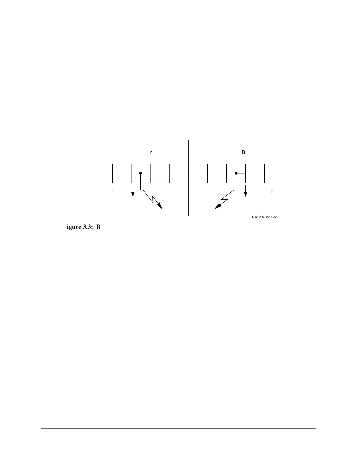
In ring-bus and breaker-and-a-half installations, two circuit breakers must operate to interrupt the
fault current. Current distribution between the two breakers is unknown until the first breaker
opens. A single breaker may initially carry the bulk of the fault current. Both breakers receive
the trip signal at the same time and are expected to operate at the same time, but the 50FT
element associated with the low current breaker may not assert until the other breaker opens.
Figure 3.3 illustrates this idea, showing the current flow if Breaker 2 fails. This causes an
uncertainty with respect to the timing of 50FT element assertion. This uncertainty is absent in a
single breaker arrangement. Timing uncertainty is accounted for in the SEL-352 Relay breaker
protection schemes intended for these complex bus/breaker arrangements. The SEL-352 Relay
is intended to protect a single breaker, regardless of the bus/breaker arrangement. In breaker-
and-a-half and ring-bus arrangements, you must use an independent breaker failure relay for
each breaker.
%UHDNHU
2SHQV
,
)
%UHDNHU
)DLOV
%UHDNHU
,V&ORVHG
,
)
%UHDNHU
,V&ORVHG
':*0
Figure 3.3: Breaker Failure in a Complex Bus/Breaker Arrangement
AVAILABLE AC CONNECTIONS
Simple breaker failure protection can be provided by monitoring only current, but the SEL-352
Relay has six ac voltage inputs for monitoring all three phases on each side of the breaker.
These six voltage inputs and the three current inputs provide complete breaker failure protection,
control, and monitoring.
The thermal logic designed to monitor the trip and close resistors of breakers is the only logic
that requires the second set of voltage connections, but much of the relay logic is enhanced if
both are connected.
Figure 3.4 shows a single-phase connection diagram of all nine ac inputs to the relay.