Date Code 20010731 Breaker Logic 3-5
SEL-352-1, -2 Instruction Manual
The protection scheme in this example protects the breaker for all failures to trip. When fault
current exceeds the minimum three-phase fault duty for a Zone 1 fault, the fault must clear in 8.5
cycles or less. All other trips must clear within 10 cycles. Because the protected breaker has trip
and close resistors, and three-phase potentials are available on both sides of the breaker, the
example uses the SEL-352 Relay trip and close resistor thermal protection schemes. Breaker
closure and flashover failures are covered.
FAULT CURRENT CONDITIONS
Application Description
The SEL-352 Relay provides five different protection schemes to detect the failure of the circuit
breaker to clear a fault. While the schemes share elements and timers, each is independent.
Enable a fault current protection scheme or customize the logic. The SEL-352 Relay applies the
single chosen scheme to all three breaker poles.
The difference among the schemes is the implementation of timers and latches that define the
breaker failure scheme.
Schemes 2 and 3 are intended for single-breaker applications and Schemes 1, 4, and 5 are
intended for multiple-breaker applications, although any of the schemes can be used in either
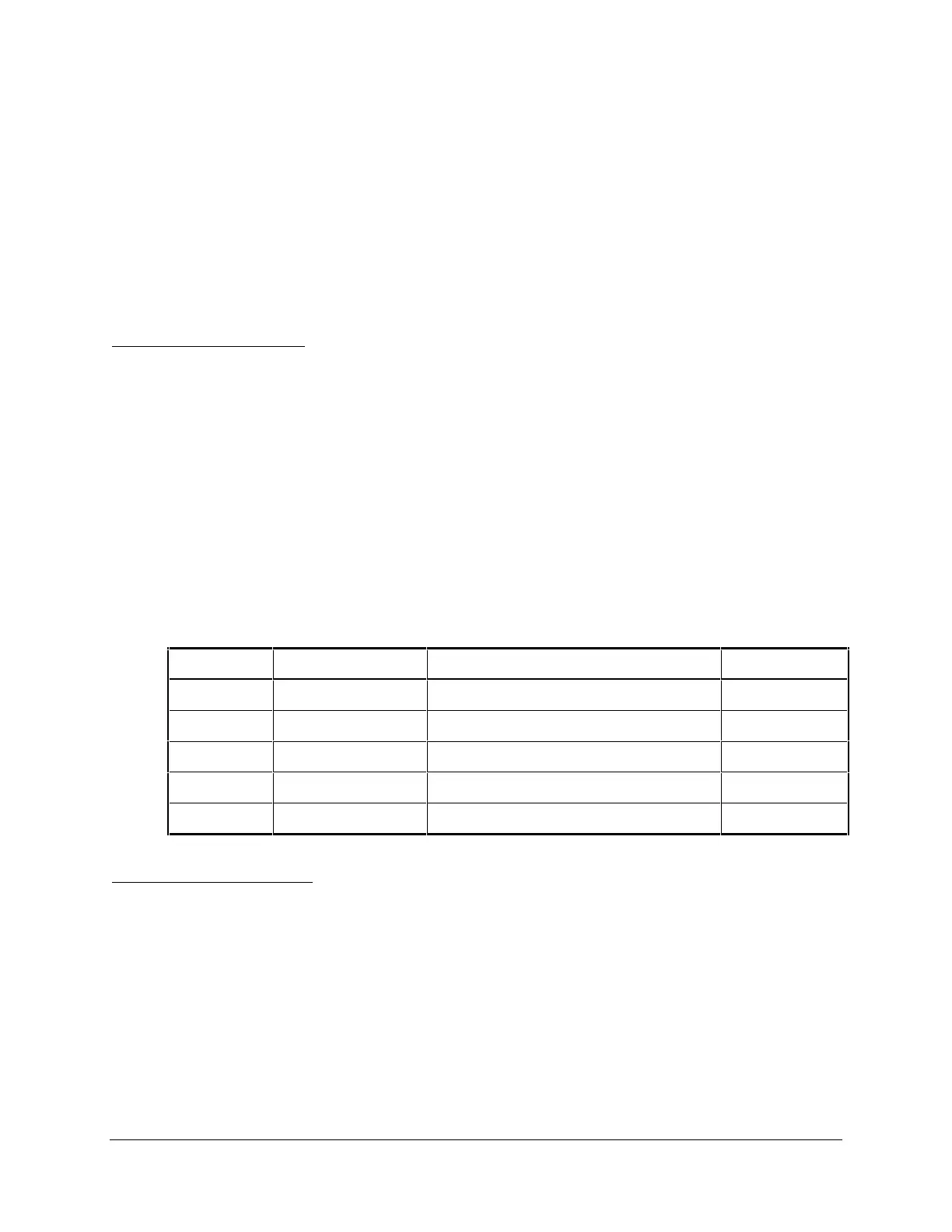
single-breaker or multiple-breaker applications. Use Table 3.2 to help select the scheme that
best fits your application. All five schemes are applicable to single-pole trip installations.
Table 3.2: Breaker Failure Scheme Selection
Breakers Pulsed Trip Inputs Breaker Failure Timer Reset By: Scheme
Single No 50FT or TRIP Dropout 3
Single Yes 50FT Dropout 2
Multiple No 50FT or TRIP Dropout 5
Multiple Yes Timer 4
Multiple Yes 50FT Dropout 1
Operating Characteristic
Figure 3.5, through Figure 3.14 show logic diagrams for A-phase logic only. In each case,
B-phase and C-phase logic are identical in form, using the respective phase trip inputs, timers,
and overcurrent elements.
Special logic has been implemented in these five schemes to improve the speed of these schemes
by detecting CT subsidence current. This logic is discussed below.
Select scheme timer settings based on the following factors:
Maximum permissible fault duration
Protective relay operating time