5-2 Control Logic Date Code 20010731
SEL-352-1, -2 Instruction Manual
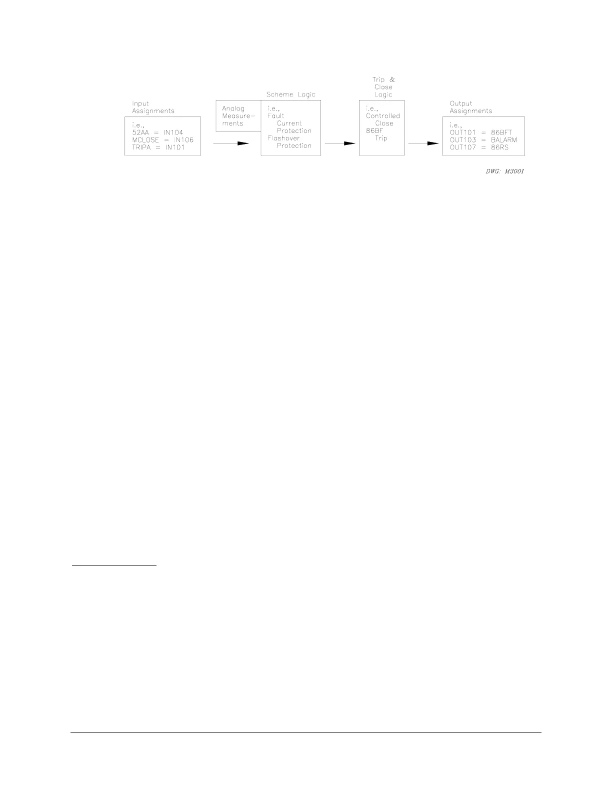
Figure 5.1: SEL-352 Relay Logic Overview Block Diagram
The relay outputs are all programmable except for the ALARM output contact. Therefore, the
relay will only close and open output contacts according to the assignments you give them.
These assignments usually are selected from the output of the Trip and Close Logic. The
predefined Trip and Close Logic allows for easy application, but the logic also can be
customized. The Trip and Close Logic gets information from the Scheme Logic, which also can
be customized. Scheme Logic gets information from analog measurements and/or digital inputs.
The relay continuously monitors all digital inputs. Assign digital inputs for specific functions.
As an example, the relay continuously monitors all digital inputs, but you can program the relay
to use IN104 for a specific function. Any time IN104 changes state, we want the relay to know
that the breaker has changed state (opened or closed). The Input Assignment would be
52AA=IN104 for A-phase. The fixed scheme logic in the relay uses 52AA to make protection
decisions along with the analog measurements. The decision, or output of the fixed scheme
logic, is used by the Trip and Close Logic. The decision, or output of the Trip and Close Logic,
is the assertion or deassertion of Relay Word bits. The following discussion describes the Relay
Word.
Up to this point, the relay has not done anything physical. It has processed data but not acted on
the information. To program the relay to open or close an output contact, you must assign one of
these Relay Word bits to an output contact like OUT101 = 86BFT, which says to close output
contact labeled OUT101 when the breaker failure lockout trip asserts. This output would
typically drive a lockout relay.
RELAY WORD BITS AND SELOGIC
·
CONTROL EQUATIONS
Relay Word Bits
The outputs of the logic in most of the figures in this section are Relay Word bits. Relay Word
bits have label names (e.g., Y59L3, 50LD, etc.). They are logic points that can have a state of:
1 (logical 1) or 0 (logical 0)
depending on the operation of the associated logic. Logical 1 represents an element being picked
up, timed out, or otherwise asserted. Logical 0 represents an element being dropped out or
otherwise deasserted. All Relay Word bits are shown in Table 5.1. The asterisk (*) in the Relay
Word is a placeholder for unused Relay Word bits. The Relay Word bits are arranged
alphabetically in Appendix F: Relay Word with descriptions and Relay Word row locations.



 To Next Page