Date Code 20010731 Control Logic 5-9
SEL-352-1, -2 Instruction Manual
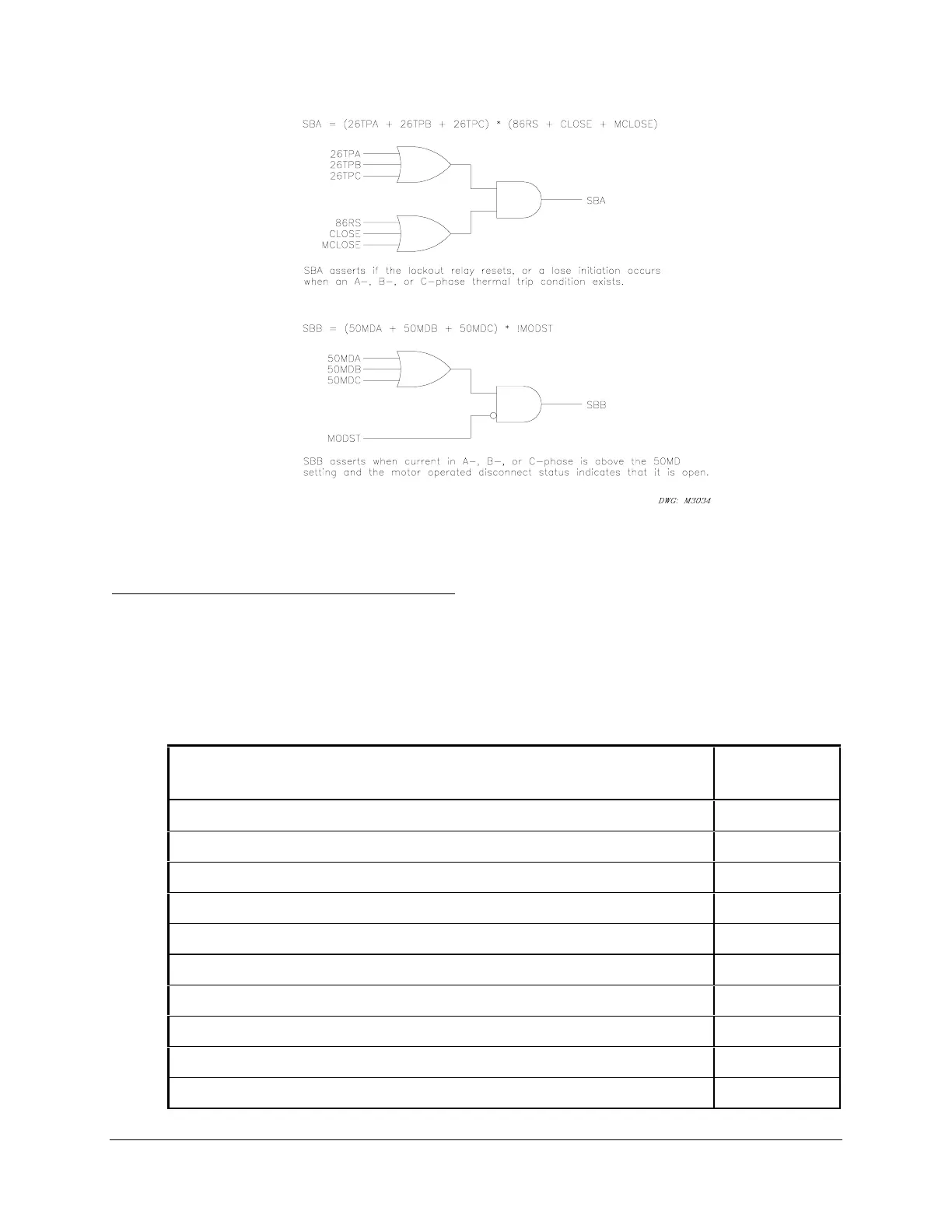
Figure 5.2: SEL
OGIC Control Equation Operators Example Diagrams
Processing Order and Processing Interval
The relay elements and logic are processed in the order shown in Table 5.5 (top to bottom).
They are processed every 1/8 or 1/4 cycle depending on the logic element. Once a Relay Word
bit is updated during a processing interval, it retains the state (logical 1 or logical 0) until it is
updated again on the next 1/8- or 1/4-cycle pass.
Table 5.5: Processing Order of Relay Elements and Logic (top to bottom)
Relay Elements and Logic
(see the Relay Word in Appendix F or Table 5.1)
Processing
Interval
Targets (Relay Word Rows 0 and 1) 1/8 cycle
General Elements, Fixed Analog Comparisons (Relay Word Rows 2–11) 1/8 cycle
General Elements, Optoisolated Inputs (Relay Word Rows 17–21) 1/8 cycle
General Elements, Input Assignment Variables (Relay Word Rows 22–23) 1/8 cycle
General Elements, Remote Bits (Relay Word Rows 12 and 13) 1/8 cycle
General Elements, Local Bits (Relay Word Rows 14 and 15) 1/8 cycle
SELOGIC Control Equation SET A Elements (Rows 24–26) 1/8 cycle
Fault Current Protection Elements (Rows 27–29) 1/8 cycle
Load Current Protection Elements (Rows 30–33) 1/4 cycle
Resistor Thermal Protection Elements (Rows 34–38) 1/4 cycle



 To Next Page