8-6 Serial Port Communications and Commands Date Code 20010731
SEL-352-1, -2 Instruction Manual
Table 8.3: Serial Communications Port Pin Function Definitions
Pin Function Definition
N/C No Connection
+5 V dc 5 V dc Power Connection
RXD, RX Receive Data
TXD, TX Transmit Data
IRIG-B IRIG-B Time-Code Input
GND Ground
SHIELD Shielded Ground
RTS Request to Send
CTS Clear to Send
DCD Data Carrier Detect
DTR Data Terminal Ready
DSR Data Set Ready
COMMUNICATIONS PROTOCOL
This section explains the serial port communications protocol used by the SEL-352 Relay. You
set and operate the SEL-352 Relay via the serial communications ports.
Note: In this document, commands you type appear in bold/upper case: SET. Keys you press
appear in bold/upper case/brackets: <ENTER>.
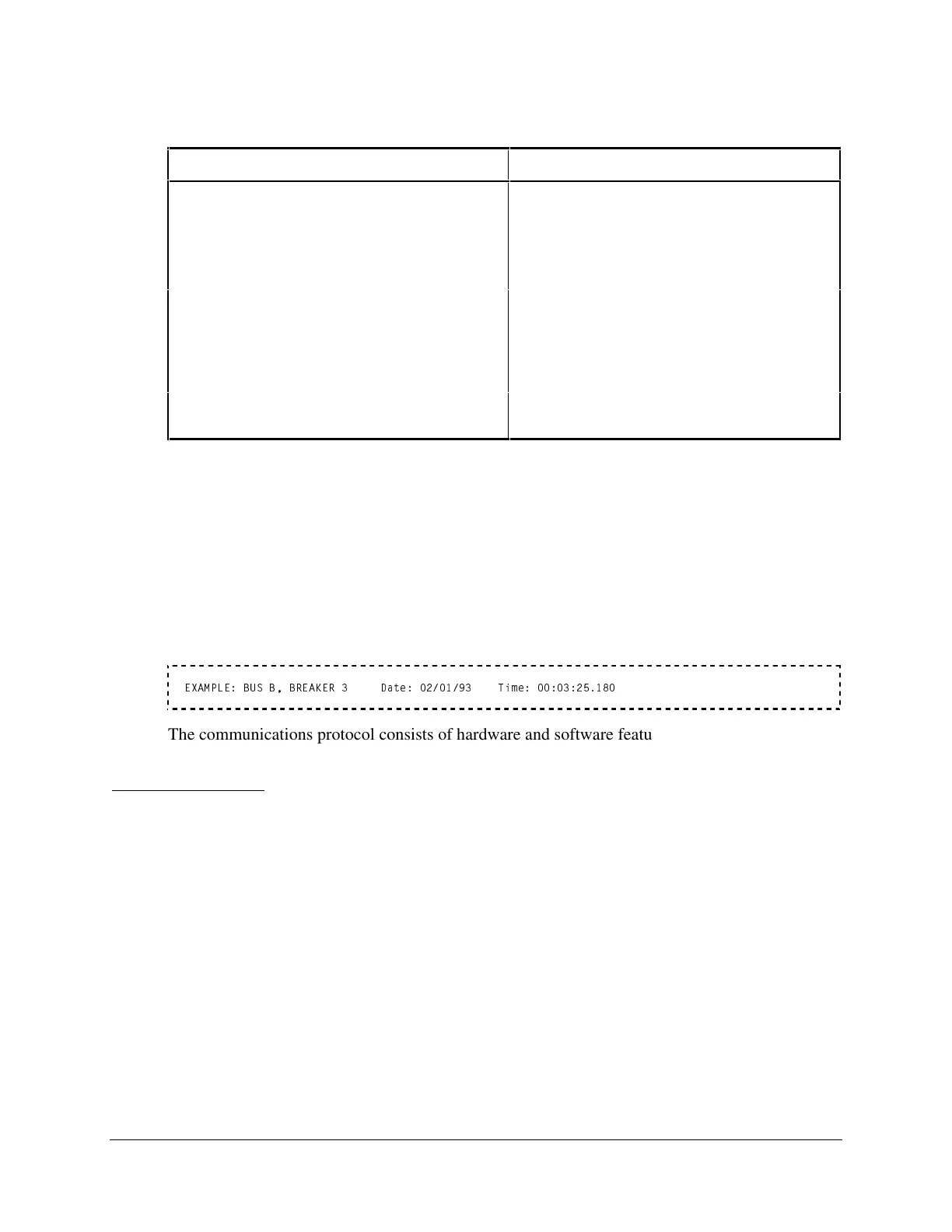
Relay output appears boxed and in the following format:
EXAMPLE: BUS B, BREAKER 3 Date: 02/01/93 Time: 00:03:25.180
The communications protocol consists of hardware and software features.
Hardware Protocol
The following hardware protocol is designed for manual and automatic communications.
1. If the SET P setting “RTS_CTS” = N, RTS will always be asserted.
2. If the SET P setting “RTS_CTS” = Y, RTS asserts while the communications buffer is less
than 87 percent full, and RTS deasserts when the communications port buffer is greater than
87 percent full.
3. If the SET P setting “RTS_CTS” = Y, the relay does not send characters until the CTS input
is asserted.



 To Next Page