Date Code 20010731 Breaker Logic 3-25
SEL-352-1, -2 Instruction Manual
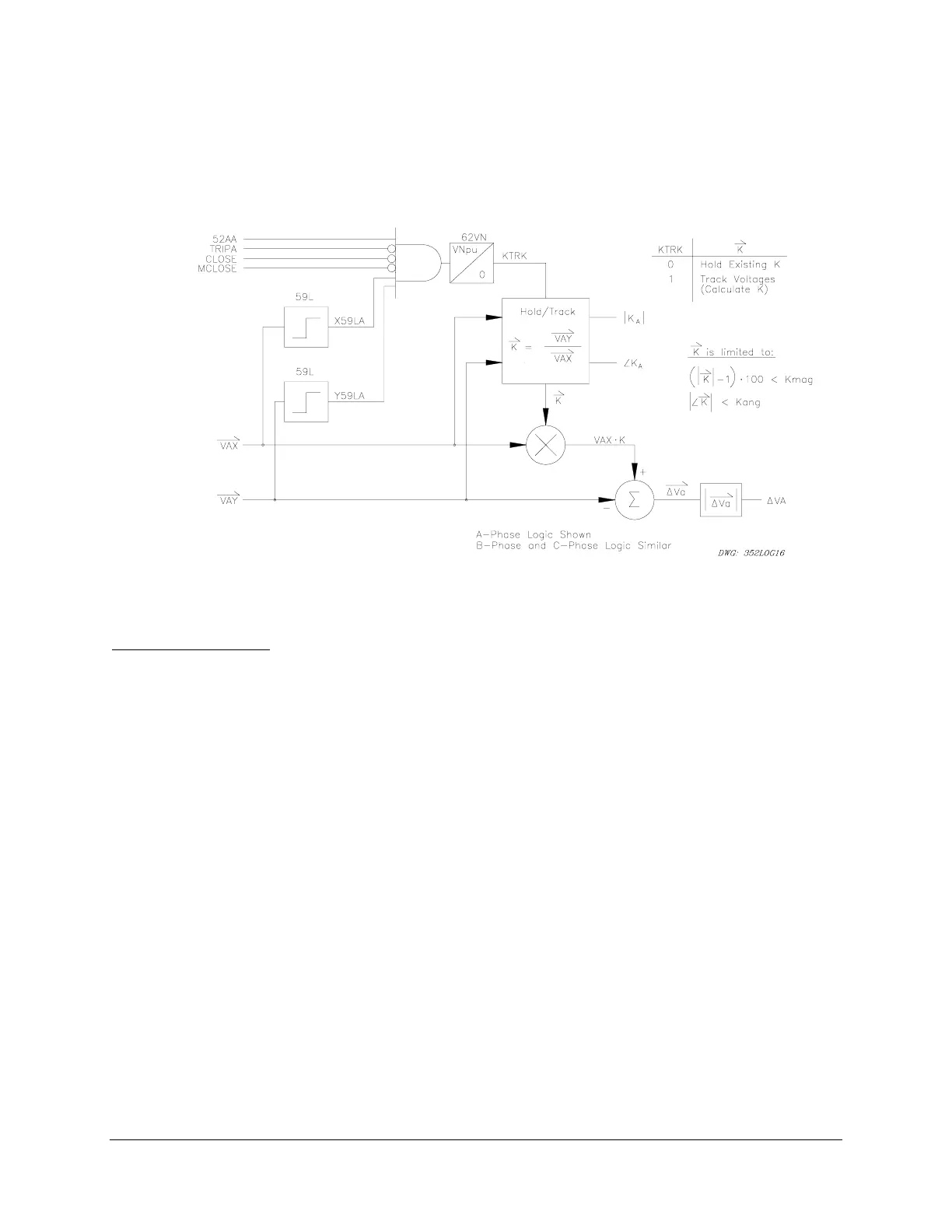
Voltage Nulling
Figure 3.20 shows the voltage nulling circuit used by the SEL-352 Relay. This circuit removes
steady-state voltage differences across the circuit breaker. The maximum nulling is based on the
Kmag and Kang settings. This logic is fixed and cannot be customized.
Figure 3.20: A-Phase Voltage Nulling Logic
Setting Description
Trip Inputs (TRIPA, TRIPB, TRIPC)
Use SET G <ENTER> to associate the breaker failure initiate logic inputs (TRIPA, TRIPB,
TRIPC) with physical inputs.
Close Signals (CLOSE, MCLOSE)
Use the SET G <ENTER> command to select either an automatic close (CLOSE) or manual
close (MCLOSE).
Any optoisolated input can be used to control these Relay Word bits. For example, if IN101 is to
be used to indicate an A-phase trip initiate from another relay, set TRIPA = IN101. If IN105 is
used to indicate an automatic close from another device, set CLOSE = IN105. Repeat this for
each programmable input. The same input may be used for all three trip conditions if single-pole
tripping is not used. The programmable input settings are actually SEL
OGIC control equations.
Use any combination of Relay Word bits according to the SEL
OGIC control equation criteria in
Section 5: Control Logic.
Breaker Status (52AA, 52AB, 52AC)
Access the three programmable breaker status inputs (52AA, 52AB, 52AC) with SET G
<ENTER>.