Date Code 20010731 Control Logic 5-5
SEL-352-1, -2 Instruction Manual
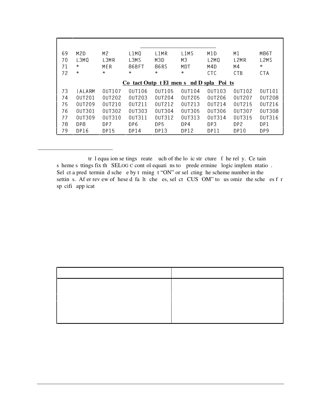
86BF Trip and Reset Elements
69
M2D
M2
L1MQ
L1MR
L1MS
M1D
M1
M86T
70
L3MQ
L3MR
L3MS
M3D
M3
L2MQ
L2MR
L2MS
71
*
MER
86BFT
86RS
MDT
M4D
M4
*
72
*
*
*
*
*
CTC
CTB
CTA
Contact Output Elements and Display Points
73
!ALARM
OUT107
OUT106
OUT105
OUT104
OUT103
OUT102
OUT101
74
OUT201
OUT202
OUT203
OUT204
OUT205
OUT206
OUT207
OUT208
75
OUT209
OUT210
OUT211
OUT212
OUT213
OUT214
OUT215
OUT216
76
OUT301
OUT302
OUT303
OUT304
OUT305
OUT306
OUT307
OUT308
77
OUT309
OUT310
OUT311
OUT312
OUT313
OUT314
OUT315
OUT316
78
DP8
DP7
DP6
DP5
DP4
DP3
DP2
DP1
79
DP16
DP15
DP14
DP13
DP12
DP11
DP10
DP9
SELOGIC Control Equations
SEL
OGIC control equation settings create much of the logic structure of the relay. Certain
scheme settings fix the SEL
OGIC control equations to a predetermined logic implementation.
Select a predetermined scheme by turning it “ON” or selecting the scheme number in the
settings. After review of these default schemes, select “CUSTOM” to customize the schemes for
specific applications, if necessary. The diagrams in this section detail the predefined logic in the
relay. See Section 7: Setting the Relay for a list of the predetermined SEL
OGIC control equation
settings that may be customized.
SEL
OGIC control equation settings are written in Boolean algebra logic, combining Relay Word
bits or Analog Compares together with different operators. (Analog Compares are discussed
later in this section.) Parentheses can also be used in SEL
OGIC control equation settings. Use
more than one set of parentheses in a given SEL
OGIC control equation setting, but they cannot be
“nested” (parentheses within parentheses). Operators in a SEL
OGIC control equation setting are
processed as shown in Table 5.2:
Table 5.2: Processing Order of SEL
OGIC Control Equation Operators
Operator Logic Function
( ) parentheses
! NOT
/ rising-edge detect
\ falling-edge detect
* AND
+ OR
The rising-edge detect (/) and falling-edge detect (\) operators sense a transition of a Relay Word
bit from one state to another, and output a logical 1 for a single processing interval if the change
is detected. The rising-edge detect senses changes from 0 to 1, the falling-edge detect from
1 to 0. The new state must be in effect for one-quarter cycle to be recognized as a state change.
The rising- and falling-edge detect operators cannot be used with Analog Compares, and each
counts as two operators toward the maximum number of 550 (Group Setting Class) or 50 (Global
Setting Class).



 To Next Page