3-4 Breaker Logic Date Code 20010731
SEL-352-1, -2 Instruction Manual
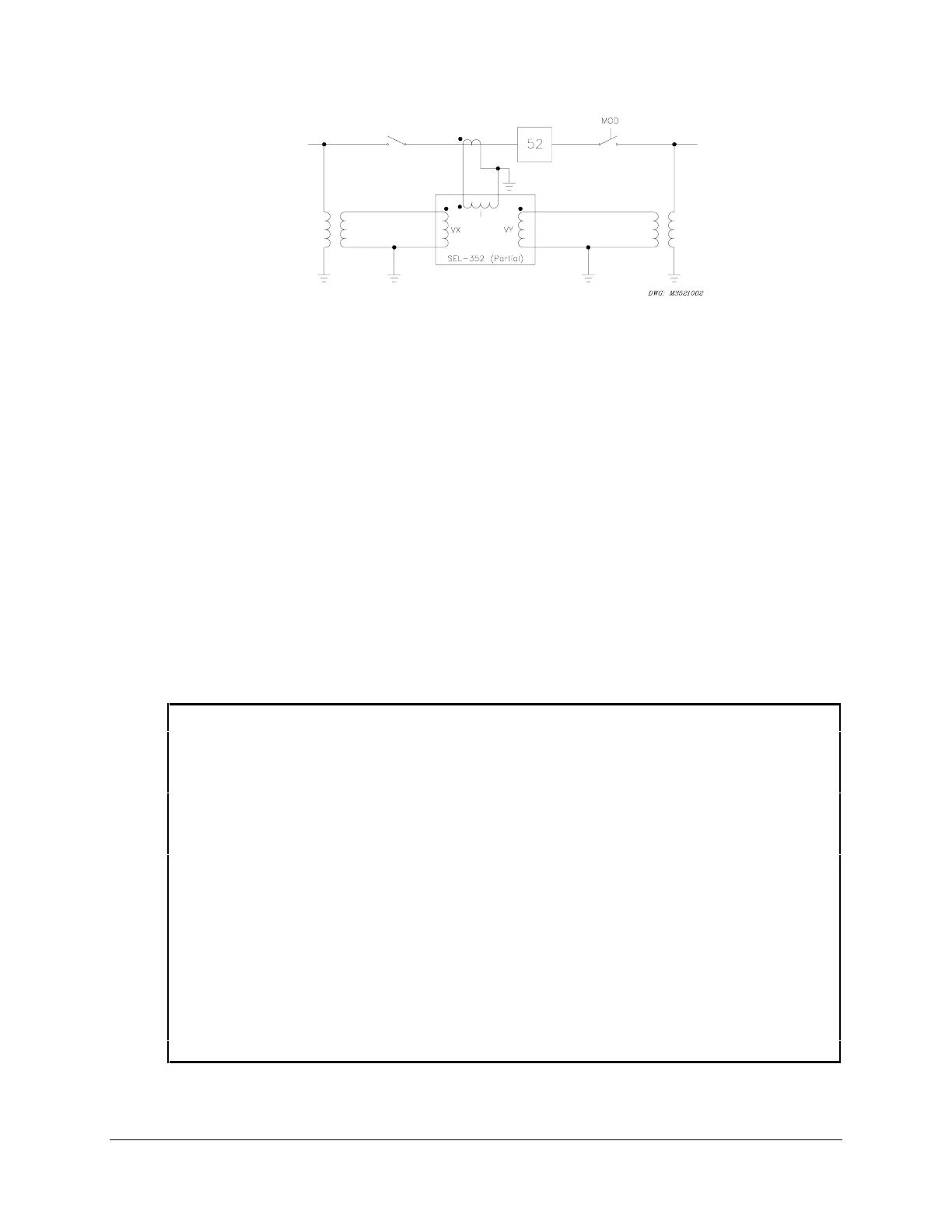
Figure 3.4: Single-Phase Diagram of AC Inputs to the Relay
Apply current to the relay from current transformers on each phase of the protected breaker.
Apply voltage to the relay from potential transformers on each side of each phase of the breaker.
The relay calculates voltage drop across each phase of the breaker by measuring each voltage
input and comparing these on a per-phase basis.
The SEL-352 Relay has voltage nulling logic to compensate for steady-state unbalance between
the voltage sources. If you do not use the voltage-based breaker protection feature, you do not
need to connect the voltage inputs.
EXAMPLE BREAKER SPECIFICATIONS
Figure 3.4 shows an example breaker arrangement. Table 3.1 lists pertinent breaker, line, and
system information that will be used to describe an application of the SEL-352 Relay for breaker
failure protection.
Table 3.1: Example Line/Breaker Information
System Per-Unit Bases:
525 kV; 100 MVA; 2756 W; 110.0 A
Line length: 100 miles
Line impedances: Z1 = Z2 = 0.0218 pu
Z0 = 0.0758 pu
Source impedances: ZS1 = 0.0034 pu
ZS0 = 0.0055 pu
Single- or three-pole tripping and closing.
Zone 1, three-phase minimum fault duty: I
3ph
= 49.6 pu = 5456 A
Line-charging current: I
c
= 350 A
CTR: 3000/5 (600/1)
PTR: 4300/1
Breaker: 500 kV, 3000 A, 3800 MVA
Maximum trip time: 33 ms
Nominal close time: 66 ms
Close resistors:
35 W/column, 2 columns
Trip resistors:
110 W/column, 2 columns
Transfer trip channel time: 0.5 cycle