Date Code 20010731 Breaker Logic 3-13
SEL-352-1, -2 Instruction Manual
%UHDNHU6XFFHVVIXOO\&OHDUV
75,3$77$
)7$
%UHDNHU
2SHUDWH7LPH
)7$
'URSRXW7LPH
6DIHW\
0DUJLQ7LPH
77SX
77$'
)DXOW2FFXUV
':*0
75,3$77$
)7$
)%)
%UHDNHU
2SHUDWH7LPH
)7$
'URSRXW7LPH
6DIHW\
0DUJLQ7LPH
77SX
77$'
)DXOW2FFXUV
%UHDNHU)DLOV
3URWHFWLYH5 HOD\
2SHUDWH7LPH
3URWHFWLYH5 HOD\
2SHUDWH7LPH
)%)
77GR
77GR
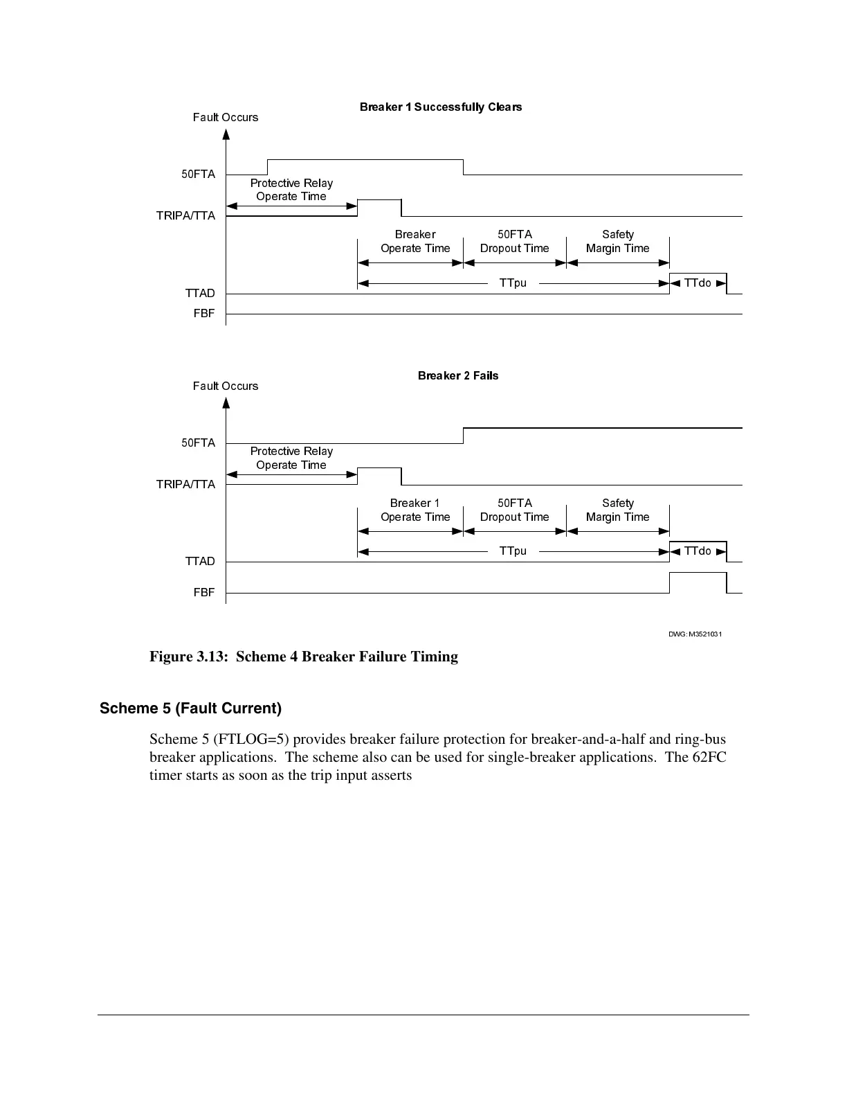
Figure 3.13: Scheme 4 Breaker Failure Timing
Scheme 5 (Fault Current)
Scheme 5 (FTLOG=5) provides breaker failure protection for breaker-and-a-half and ring-bus
breaker applications. The scheme also can be used for single-breaker applications. The 62FC
timer starts as soon as the trip input asserts to provide consistent breaker failure clearing times
between adjacent breakers. This logic is necessary in multiple-breaker applications because the
fault current may be below the fault current threshold for one breaker until the adjacent breaker
clears.
The logic shown in Figure 3.14 protects the system from a breaker failure during a fault.
Scheme 5 is intended for use in single breaker, breaker-and-a-half, and ring-bus arrangements.
When the TRIPA input is asserted, the 62FC timer starts. If 50FTA is asserted when the 62FC
timer expires, the Relay Word FBF bit asserts. If the TRIPA input is deasserted or the 50FTA
element drops out before 62FC expires, the logic resets and FBF does not assert.