3-12 Breaker Logic Date Code 20010731
SEL-352-1, -2 Instruction Manual
)DXOW2FFXUV
3URWHFWLYH5HOD\
2SHUDWH7LPH
75,3$
)7$
)&$
)&$'
)%)
%UHDNHU
2SHUDWH7LPH
)7$
'URSRXW7LPH
6DIHW\
0DUJLQ7LPH
)&SX
':*0
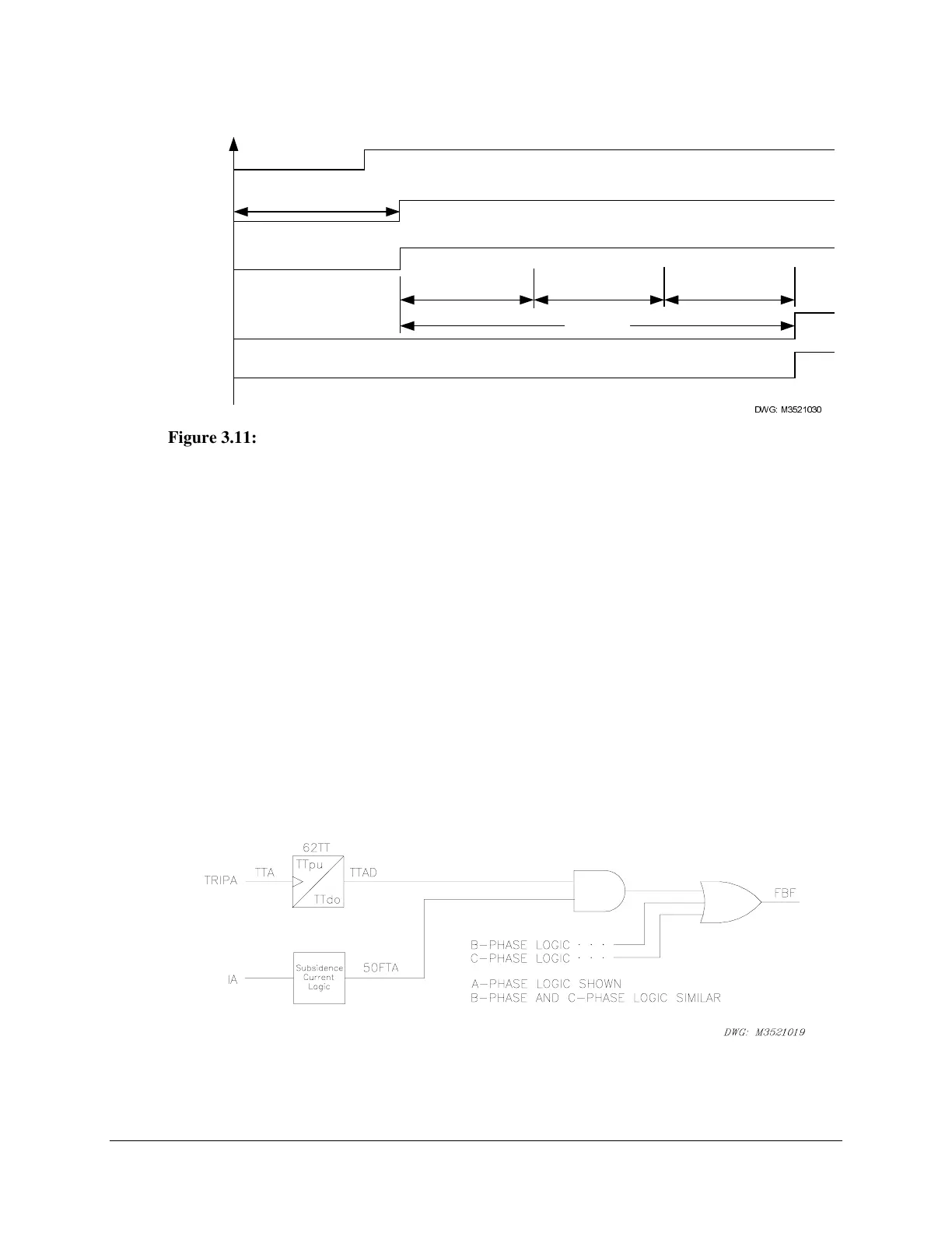
Figure 3.11: Scheme 3 Breaker Failure Timing
Scheme 4 (Fault Current)
Scheme 4 (FTLOG=4) provides breaker failure protection for breaker-and-a-half and ring-bus
breaker applications. The scheme also can be used for single-breaker applications. This scheme
adds a latch and dropout timer to the pickup timer (represented by a single symbol) of Scheme 5
to allow for a pulsed trip input. The 62TT timer latches the trip input when the TRIPA input
asserts for at least a quarter-cycle. The 62TT timer output (TTAD) remains deasserted for time
TTpu, after which it asserts for time TTdo. Relay Word bit FBF asserts if 50FTA asserts while
the 62TT timer output is asserted. The 62TT breaker failure timer resets when the 62TT timer
dropout time (TTdo) expires. This timing scheme provides consistent breaker failure clearing
times between adjacent breakers. This logic is necessary in multiple-breaker applications
because the fault current may be below the fault current threshold for one breaker until the
adjacent breaker clears.
The Scheme 4 logic, shown in Figure 3.12, protects the system from a breaker failure during a
fault. This scheme is applicable to single breaker, ring-bus, and breaker-and-a-half bus
configurations.
Figure 3.12: A-Phase Failure to Trip for Fault Logic, Scheme 4
 Loading...


