Date Code 20010731 Close Logic 4-13
SEL-352-1, -2 Instruction Manual
on-wave closing. These are available on Interface Board 5. See Section 2: Installation. The
logic and output contact operations occur in 200 ms or less. This output contact assignment is
different from the standard output contact assignments (OUT101 = 86BFT). The point-on-wave
logic directly controls the output contact hardware specified by the close settings CLSA, B, and
C. The standard output assignments also control the output contacts, but only every 1/8 cycle.
CLSA, B, and C control the outputs immediately. The default settings are OUT301, OUT302,
and OUT303.
Setting Calculation
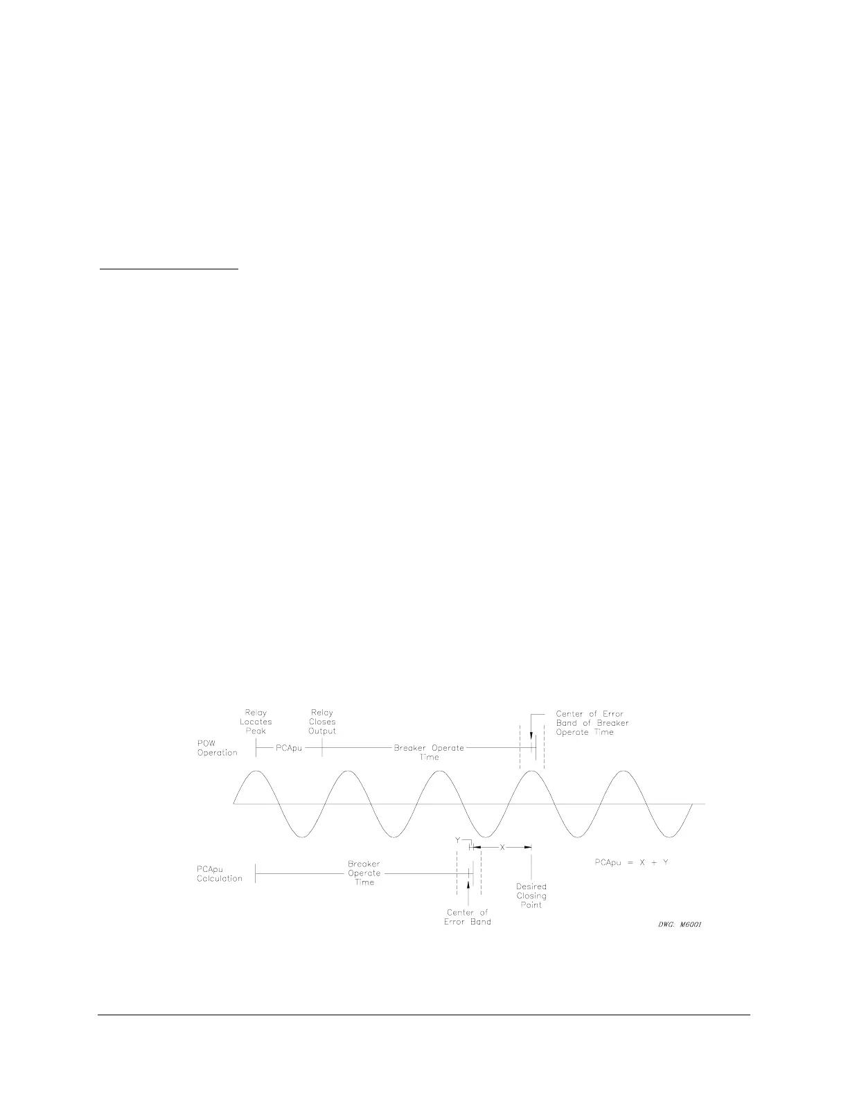
Point-On-Wave Timer Pickup (PCApu, PCBpu, PCCpu)–Scheme 2
Detection of a positive trapped charge causes the logic to close the relay output contact at a
positive peak. For negative trapped charge, the logic closes the output contact at a negative
peak. The PCApu timer provides the delay for the breaker close time and any offset to move the
closing point to another point on the wave.
For example, with a Tclose (nominal closing time of the breaker) time of 33 ms (2 cycles) and a
setting of PCApu = 0, the breaker will close at the appropriate peak 2 cycles after the output
contact closes. However, if the Tclose time is 29 ms (1.75 cycles), the breaker would close 1/4
cycle before the peak.
To set PCApu for breaker and offset times that are not multiples of 1 cycle, subtract the
fractional part from 1 cycle and set PCApu to this number. For example, the 1.75-cycle breaker
requires a PCApu setting of 1 minus the fractional part of 1.75 (0.75), which equals 0.25 (1–0.75
= 0.25). PCApu is set in ms; therefore, PCApu = 4.17 ms for a nominal 60 Hz system.
An offset may be included in the timer as well. For example, a breaker that nominally closes in
38.9 ms but has a tolerance of 0.5 ms for temperature variation, and +1/–2 ms for control
voltage variation, needs an offset to provide the best closing results. The total error band is
+1.5/–2.5 ms. This error band should be centered around the point of closing. It needs to shift
0.5 ms in the positive direction. Set PCApu = [1 – fractional part of (38.9/16.67)] • 16.67 + 0.5 =
11.61 ms.
Figure 4.10: Point-On-Wave Timer Calculation



 To Next Page