Date Code 20010731 Installation 2-33
SEL-352-1, -2 Instruction Manual
Interface Board 6 (12 Outputs, 8 Inputs)
Optoisolated Inputs
All eight control inputs are dry optoisolated inputs and are not polarity dependent. Input options
are 24 Vdc standard or 48, 110, 125, or 250 Vdc level sensitive. Control voltage must be
specified when ordering. To assert an input, apply control voltage to the terminals assigned to
that input. Each input is individually isolated, and a terminal pair is brought out for each input.
There are no internal connections between inputs. See General Specifications in Section 1:
Introduction and Specifications for ratings.
Output Contacts
30 A make
6 A carry
10 A interrupt for L/R <0.04 seconds at 125 Vdc
10 A interrupt for L/R <0.02 seconds at 250 Vdc
Closing (pickup for “a” contacts, dropout for “b” contacts): 1/4-cycle or less
Opening (dropout for “a” contacts, pickup for “b” contacts): 1/2-cycle or less (typical is
1/4-cycle)
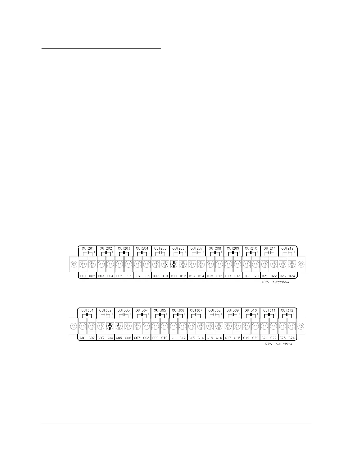
Interface Board 6 provides 12 output contacts. These 12 High Current Interrupting dry output
contacts can interrupt 10 A of inductive current with an L/R <0.04 seconds at 125 Vdc. At 250
Vdc, they will interrupt 10 A of inductive current for an L/R <0.02 seconds. These outputs are
polarity dependent. Notice the polarity mark above terminal B02 and C02 in the following
figures that are similar to the rear of the relay:
Figure 2.31: Interface Board 6 Output Contacts (Board Position 1)
Figure 2.32: Interface Board 6 Output Contacts (Board Position 2)
Configure the output contacts as “a” contacts or “b” contacts with solder jumpers. Figure 2.33
and Figure 2.34 show the locations of the jumpers and explain the jumper positions. Contacts
are factory configured as “a” contacts.
Note: The plug-in connector version of this board has only four jumper-configurable outputs
(see Figure 2.34.)