Date Code 20010731 Breaker Logic 3-11
SEL-352-1, -2 Instruction Manual
)DXOW2FFXUV
3URWHFWLYH5HOD\
2SHUDWH7LPH
75,3$
)7$
)&$
)&$'
)%)
%UHDNHU
2SHUDWH7LPH
)7$
'URSRXW7LPH
6DIHW\
0DUJLQ7LPH
)&SX
':*0
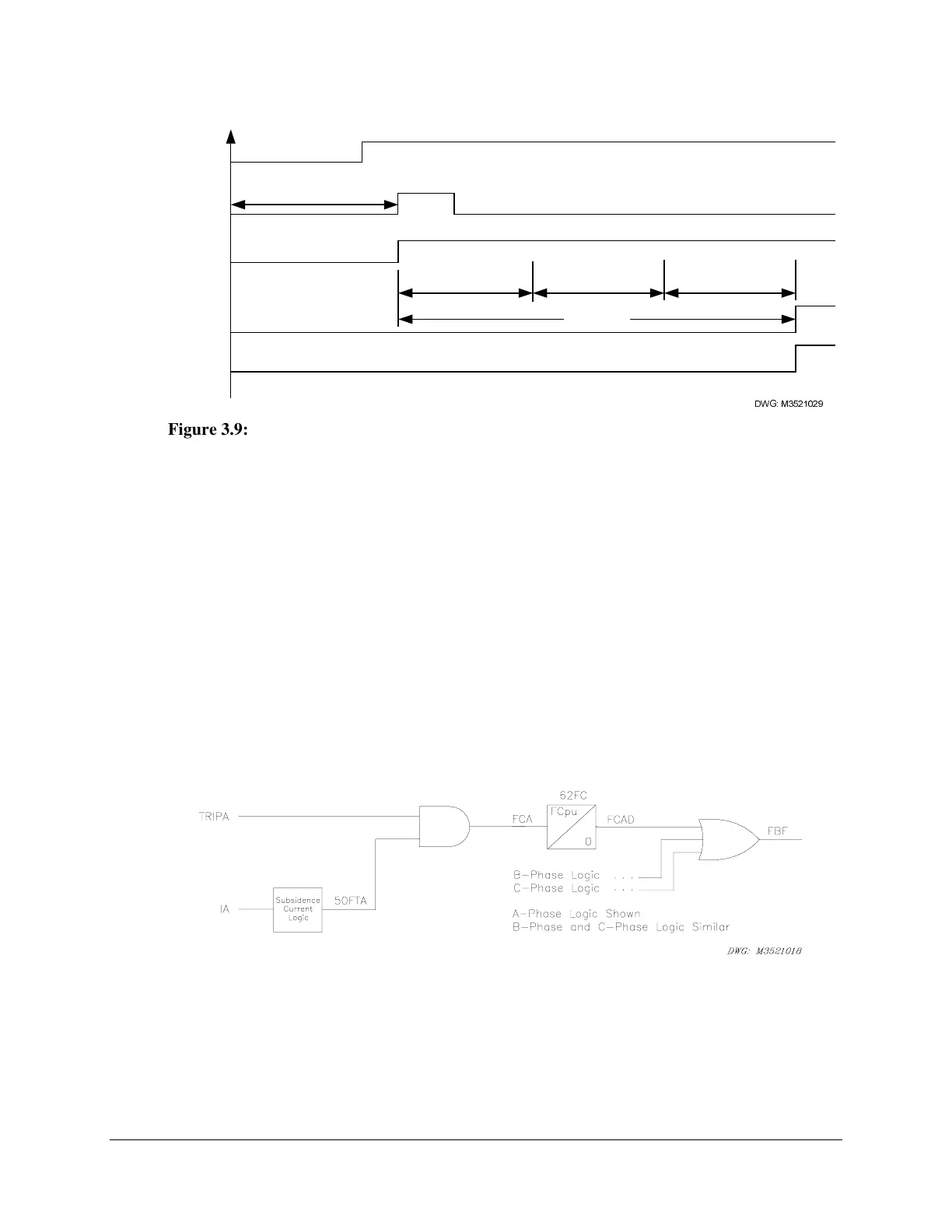
Figure 3.9: Scheme 2 Breaker Failure Timing
Scheme 3 (Fault Current)
Scheme 3 (FTLOG=3) provides breaker failure protection logic for single-breaker applications.
It also may be used for multiple-breaker applications where sequential/delayed tripping is
acceptable. This scheme requires the continuous assertion of both the 50FT fault current
detector and the trip input to time for a breaker failure.
The logic shown in Figure 3.10 protects the system from a breaker failure during a fault. This
scheme is applicable to single breaker configurations. When a fault occurs, 50FTA asserts, and
the protective relay asserts the relay TRIPA input. The AND gate output goes high, and the
62FC timer starts. If the TRIPA input and 50FTA element remain asserted until 62FC expires,
Relay Word bit FBF asserts.
In Scheme 3, the trip input must remain asserted while current flows in the protected breaker.
Scheme 3 resets when either the TRIPA input deasserts or the 50FTA element drops out.
Figure 3.10: A-Phase Failure to Trip for Fault Logic, Scheme 3