3-20 Breaker Logic Date Code 20010731
SEL-352-1, -2 Instruction Manual
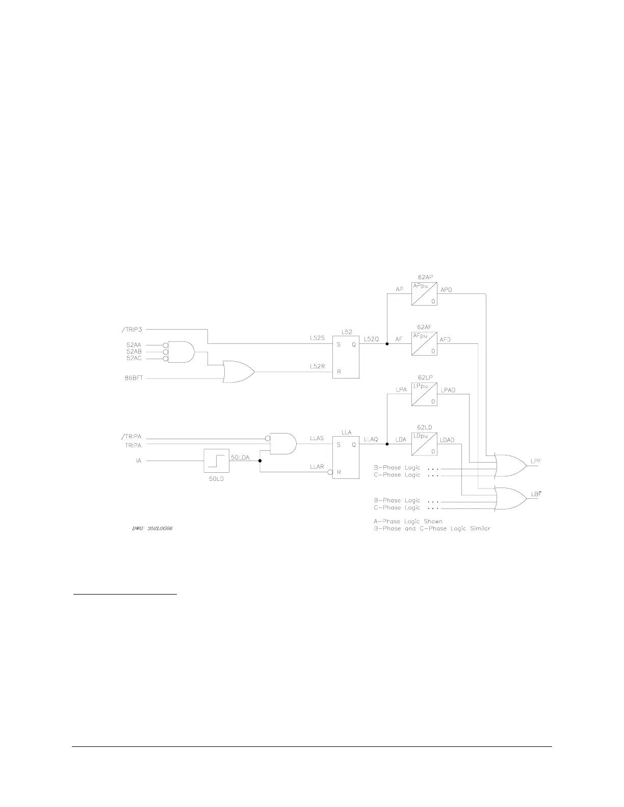
Scheme 2 (Load Current With 52a Backup)
If there are conditions under which the protected breaker could be called to trip, while current is
below the 50LD overcurrent element setting, you may want to use Scheme 2. Scheme 2
(Figure 3.18) is identical to Scheme 1 (Figure 3.17), except that it adds 52A supervised breaker
failure timers APpu and AFpu. An application where this function might be required is when the
protected circuit breaker is connected to a generator-transformer unit.
In this instance, the circuit breaker could be issued a trip signal while the generator is idling.
Under these conditions, current through the protected breaker is nearly zero. You can set the
SEL-352 Relay to operate the 86 lockout relay if the relay 52A input is not deasserted after a
settable time delay.
If any other breaker failure condition is detected based on assertion of the 86BFT bit, the 52A
logic of Scheme 2 is disabled.
Figure 3.18: Failure to Trip Load or Line-Charging Current Logic, Scheme 2
Setting Description
Trip Inputs (TRIPA, TRIPB, TRIPC)
Use SET G <ENTER> to associate the breaker failure initiate logic inputs (TRIPA, TRIPB,
TRIPC) with physical inputs. Both load current protection schemes use the three programmable
inputs: TRIPA, TRIPB, and TRIPC.
Any optoisolated input can be used to control these Relay Word bits. For example, if IN101 is
used to indicate an A-phase trip initiate from another relay, set TRIPA = IN101. If IN104 is used
to indicate breaker status, set 52AA = IN104. Repeat this for each programmable input. The