Date Code 20010731 Installation 2-17
SEL-352-1, -2 Instruction Manual
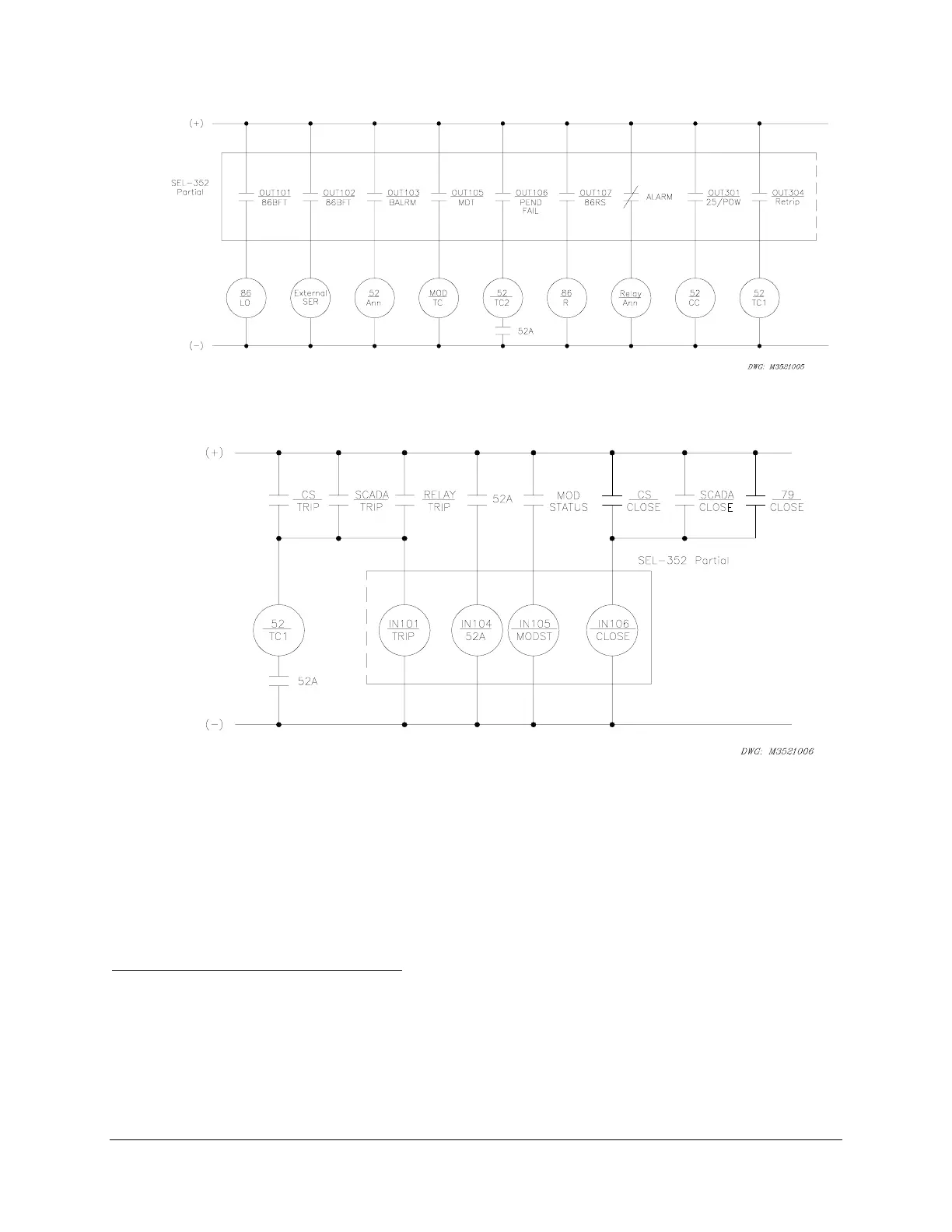
Figure 2.14: SEL-352 Relay Example DC Output Contact Connections
Figure 2.15: SEL-352 Relay Example DC Input Connections
CIRCUIT BOARD CONFIGURATION
In this section we describe (1) how to remove the relay circuit boards so you can change circuit
board jumpers or replace the clock battery and (2) how to replace the circuit boards in the relay.
Accessing the Relay Circuit Boards
1. De-energize the relay by removing the connections to rear-panel terminals + (Z25) and
– (Z26). Accomplish this easily on Connectorized relays by removing the connector at
rear-panel terminals + (Z25) and – (Z26).
2. Remove any cables connected to serial ports on the front and rear panels.

 Loading...


