3-6 Breaker Logic Date Code 20010731
SEL-352-1, -2 Instruction Manual
Protected breaker operating time
50FT element dropout time
Operating times of electrically adjacent breakers
Desired breaker failure operating safety margin
If an auxiliary interposing relay is used between the protective relay trip output and the breaker
fail initiate (TRIPA, TRIPB, TRIPC) input to the SEL-352 Relay, you must also account for the
operating time of the auxiliary relay. Be aware that different models of auxiliary relays have a
wide variety of operating times. Most scheme operating considerations are listed in Table 3.2.
Additional timing considerations and recommended settings are listed below by scheme number.
Subsidence Current Logic
In schemes for detecting breaker failure to clear a fault, it is important to be able to detect as
quickly as possible not only the pickup but the dropout of fault-detecting overcurrent elements.
Half-cosine filtering is used to accelerate this detection of element pickup and dropout.
However, the dropout detection can be delayed by a phenomenon called CT subsidence current.
This current may appear as a small exponentially decaying dc current with a fairly long time
constant. The effect of this current upon the half-cosine filter may be to create artificial phasor
magnitudes large enough to prevent proper detection that the primary ac current actually has
been interrupted. This failure to detect interruption of the primary ac current may delay
detection of overcurrent element dropout by some fraction of a cycle. As a result, longer time
coordination intervals must be used in the breaker failure logic to preserve security. The
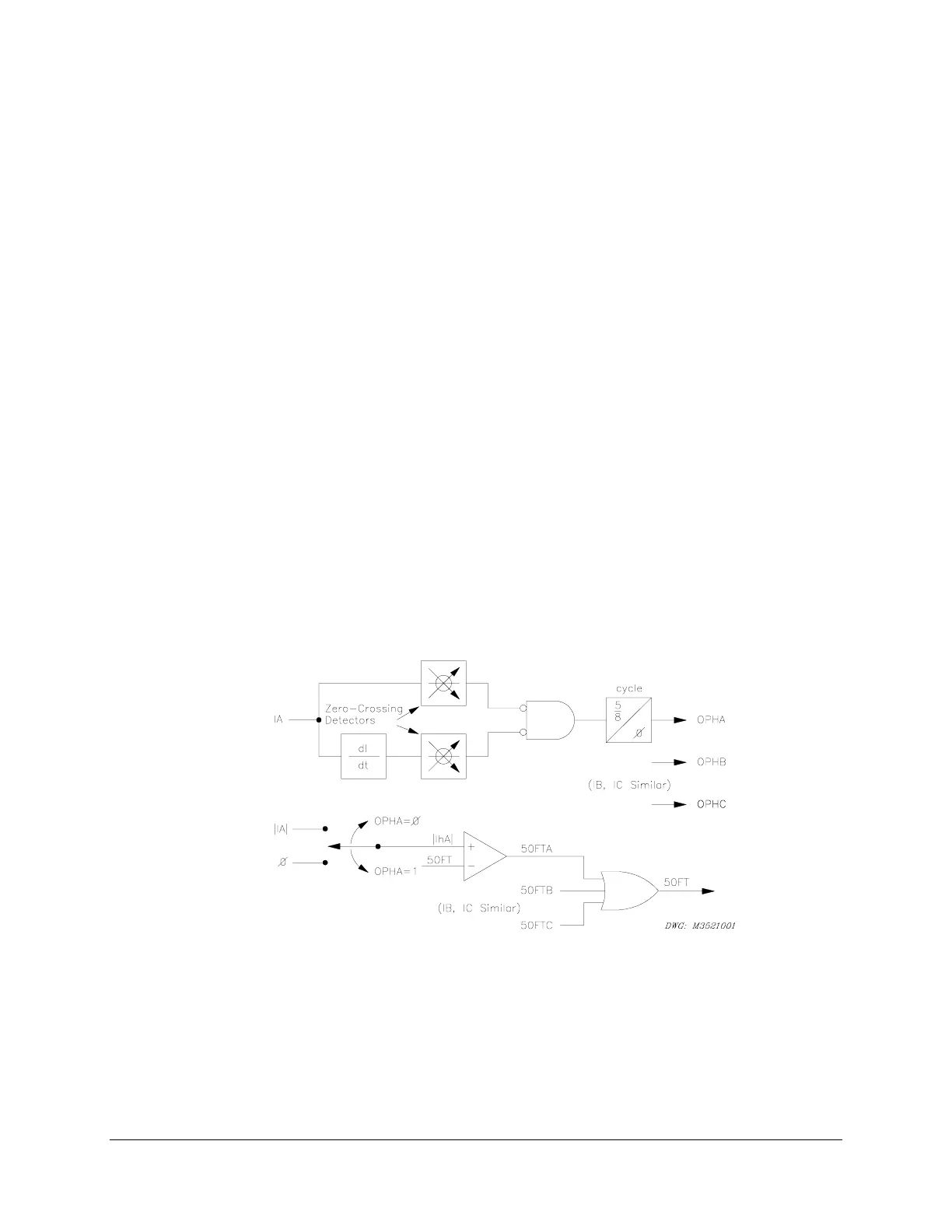
SEL-352 Relay employs an innovative logic for detecting the presence of subsidence current,
thereby speeding the detection of overcurrent element dropout. The logic is shown in Figure 3.5,
for A-phase current. B-phase and C-phase logic schemes are similar.
Figure 3.5: Subsidence Current Logic
In the upper drawing, the raw ac input current IA and the first derivative of IA are examined for
zero crossings. The logical outputs of the two zero-crossing detectors are inverted and passed
through an AND gate to a timer with a 5/8-cycle pickup time. With normal ac current flowing as
IA, there are sufficient zero-crossing detections that the output of the AND gate never stays at
logical 1 long enough to pick up the timer. Therefore, the internal control bit OPHA (A-phase
open) stays at logical 0. In the lower drawing, with OPHA = 0, the “switch” causes the



 To Next Page