3-2 Breaker Logic Date Code 20010731
SEL-352-1, -2 Instruction Manual
If the breaker fails to clear a fault, all electrically adjacent breakers must open. Opening these
adjacent breakers stops a continuing fault and interrupts current flow in the failed breaker.
Figure 3.1 shows a basic breaker failure scheme. TRIPA, TRIPB, and TRIPC are used as the
breaker failure initiate inputs from the local primary and backup protection. The 50 overcurrent
element is set to pick up for specific current levels. For high fault current levels, the 50 element
should be immune to dc and reset quickly when the protected breaker opens. For lower current
levels, the 50 element should be secure, immune to dc and exponentially decaying ramp currents.
When the timer expires, it closes an output contact to energize the 86 lockout relay, which
initiates local tripping of all electrically adjacent breakers. Optionally, the 86 lockout relay can
initiate transfer tripping to clear electrically adjacent remote breakers.
Figure 3.1: Basic Breaker Failure Protection Scheme
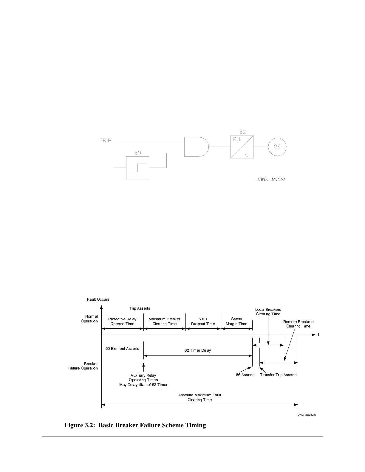
Time delay selection is important. Figure 3.2 illustrates the timing of the basic breaker failure
scheme. Calculate an absolute maximum fault clearing time based upon system stability and
equipment I
2
t withstand considerations. In the event of a breaker failure, total time to clear all
electrically adjacent breakers must be less than this absolute maximum. The 62 timer pick up
delay should be set to allow time for the protected breaker to operate and the 50 element to reset.
Also, a short safety margin should be added. The amount of time available for a safety margin is
limited by the operating time of the protective relays and the local and remote breakers.
When the failed breaker is isolated by disconnect switches or when a breaker is removed from
service for maintenance and testing, the breaker failure scheme should be disabled. This
prevents inadvertent tripping of other breakers in service.
)DXOW2FFXUV
1RUPDO
2SHUDWLRQ
': *0
3URWHFWLYH5HOD\
2SHUDWH7LPH
7ULS$VVHUWV
)7
'URSRXW7LPH
6DIHW\
0DUJLQ7LPH
0D[LPXP%UHDNHU
&OHDULQJ7LPH
W
(OHPHQW$VVHUWV
%UHDNHU
)DLOXUH2SHUDWLRQ
7LPHU'HOD\
$X[LOLDU\5HOD\
2SHUDWLQJ7LPHV
0D\'HOD\6WDUWRI7LPHU
$EVROXWH0D[LPXP)DXOW
&OHDULQJ7LPH
7UDQVIHU7ULS$VVHUWV$VVHUWV
/RFDO%UHDNHUV
&OHDULQJ7LPH
5HPRWH%UHDNHUV
&OHDULQJ7LPH
Figure 3.2: Basic Breaker Failure Scheme Timing